B-6.2 Identify Types of Welds, Positions, Joints and Symbols
Identify Weld Types
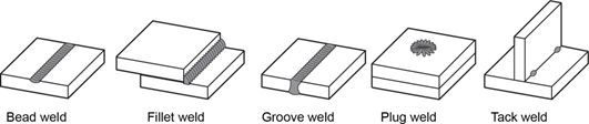
There are five types of welds used in non-pressure welding (Figure 1):
- Bead weld
- Tack weld
- Fillet weld
- Groove weld
- Plug and slot weld
Bead Welds
Bead welds are single-pass deposits of weld material used to build up the surface of metal or to replace metal on worn surfaces. Bead welds used for this application are commonly called hardsurfacing or hardfacing.
Tack Welds
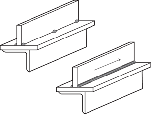
Tack welds are a series of short welds used to hold the joint assembly in place during the fit-up procedure (Figure 2). Each tack weld is a short (sometimes temporary) weld approximately 13 mm ([latex]\frac{1}{2} \text{"}[/latex]) in length. Tack welds are usually deposited at both ends of the joint and at approximately equal intervals along the length of the joint.
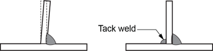
On tee joints, tack welds are often used along the opposite side of the weld to prevent the upright plate from leaning toward the weld (Figure 3).
Fillet Welds
Fillet welds are used extensively on lap, tee, and corner joints where they join two pieces of metal that are usually at right angles (90°) to each other. A fillet weld consists of one or more beads or layers that are roughly triangular in cross-section. The features of a typical fillet weld on a tee joint are shown in Figure 4.
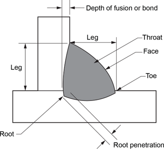
The ideal fillet weld is characterized by:
- Joint faces at right angles (90°)
- Face that is flat or slightly convex
- Toes that merge smoothly with the surface of the joint members
- Legs of equal length
In many cases, fillet welds are more economical than groove welds, in that they are easier to assemble and require less edge preparation. They generally require more weld material and are less able to withstand high stress loads.
Fillet welds are not considered capable of carrying stress loads unless their length is at least four times the size of the weld. Stress-carrying fillet welds connecting material up to 25 mm (1″) thick should not be less than 10 mm ([latex]\frac{3}{8} \text{"}[/latex]) in size.
Groove Welds
Groove welds fill in the gap or groove between two pieces of metal. Groove welds are most commonly used on butt joints, although the weld on an open corner joint or on specially prepared lap and tee joints can sometimes be considered a groove weld.
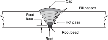
Groove welds consist of a root bead, a hot pass, fill passes and a cap (Figure 5). The number of passes will vary, depending on the thickness of the material. On thinner metal, the hot pass and fill pass can be combined into one pass and, in some cases, a single pass is adequate for the entire weld.
The significant dimensions of groove welds are shown in Figure 6. These include the root opening, the root face (or landing), the included angle, the thickness and the throat. On bevelled joints, the bevel angle is important and, on joints with a J preparation, the root radius is significant.
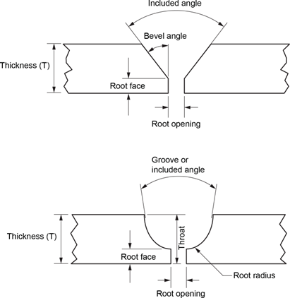
The size of the root opening, the root face, the included angle, and the root radius all have bearing on the amount of weld material required and on the depth of penetration. For example, too large a root opening, face or included angle will result in excessive penetration and the deposition of unnecessary weld metal, while dimensions that are too narrow will make full penetration extremely difficult, if not impossible. If the root radius on a U-joint is too great, an excessive amount of weld material will be deposited and the possibility of uncontrollable distortion increases.
The selected dimensions for these dimensions will depend on the material thickness, electrode size and the welding process.
Groove Weld Size and Profile
The size of groove welds is determined by the depth of weld penetration in the groove or gap between the two pieces. In Figure 7, the weld size in A (where penetration is complete) is the same as the thickness of the plate. Where penetration is incomplete, as in B, the weld size is the depth of the penetration. In C (where the plates differ in thickness and there is complete penetration), the weld size is the thickness of the thinner plate.

Metal deposited above the surface of the plate is called reinforcement. Profiles of groove welds show the amount of reinforcement at the centre of the weld bead (Figure 8). This reinforcement must not exceed 3 mm ([latex]\frac{1}{8} \text{"}[/latex]) as excessive reinforcement is uneconomical and contributes nothing to the strength of the weld. It decreases the working strength of the joint because stresses concentrate at the toe of the weld.
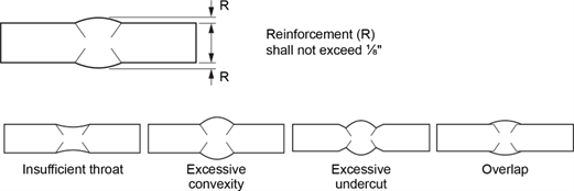
Reinforcement may be removed by gouging or it must be built up uniformly from the surface of the parent metal to the maximum 3 mm ([latex]\frac{1}{8} \text{"}[/latex]) at the centre of the weld. There must be no valley or groove along the edge or in the centre of the weld.
The width of a groove weld should not extend more than 3 mm ([latex]\frac{1}{8} \text{"}[/latex]) beyond the shoulder or edge of the joint on either side. Extra deposit beyond this is uneconomical because there is no corresponding increase in joint strength.

If you’re unsure which weld to use, start by identifying the joint type first.
Five Basic Joint Types
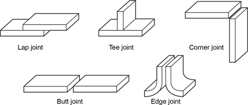
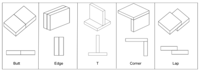
There are five basic weld joints used in welding (Figures 9 and 10). Within these five, however, are many variations and the selection of a particular joint or variation is based on four important factors:
- The load applied to the weld (for example, compression, torsion, bending, or fatigue)
- The way the load is applied (for example, sudden, variable, or steady)
- The thickness of the base metal
- The cost of the joint preparation and welding time
The five basic weld joints are defined below:
Butt Joint: A joint that joins two pieces of metal in the same plane.
Corner Joint: A joint that joins two pieces of metal at right angles, formed at the ends of both pieces in an L shape.
Edge Joint: A joint that joins two pieces of metal that are turned up at the edges; also known as a flange joint.
Lap Joint: A joint that joins two pieces of metal that overlap one another.
Tee Joint: A joint that joins two pieces of metal at right angles, forming a “T” shape.
Variations in Joint Design
Variations in the five basic designs are a result of the different preparations that can be applied to the edges of the joint. Edge preparation is necessary on thicker material to ensure full penetration of the joint.
Tee Joints
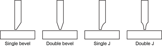
The square tee joint requires no edge preparation and is widely used because it is relatively inexpensive and easy to fit. On thicker material, the edges may be prepared with a single bevel, double bevel, single J or double J (Figure 11).
Tee joints that are welded on only one side (single-welded) are satisfactory for only light static loads. For heavy or fluctuating loads, tee joints need to be welded on both sides (double-welded) to increase their strength.
Tee joints are relatively easy to design and they provide maximum access for welding, however, there is a high possibility of distortion. An additional drawback is the expense of tee joints in terms of the weld material, especially on larger tee joints and on joints that need to be welded from both sides.
Lap Joints
Lap joints require little or no edge preparation. On thicker material, a single bevel is all that is usually required. Lap joints are often selected for welds between two materials that have different thickness.
For welds that do not require great strength, a single lap joint may be selected to provide a “tight” joint. However, single lap joints must not be used for welds that will be subjected to fluctuating, bending or twisting loads. For these types of loads, the joint can be welded from both sides, or a double lap joint can be selected (Figure 12).

Lap joints have two significant drawbacks. As with tee joints, the material requirements are high, so maximum tensile strength can only be achieved when the overlap is five times the thickness of the thinner member. Also, under stress loading, the joint tends to lose its strength.
Corner Joints
There are two types of corner joints, the open corner and the closed corner (Figure 13).
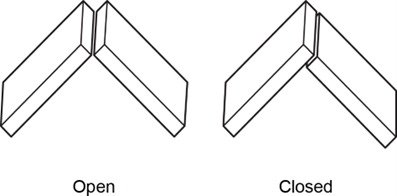
The open corner joint is more frequently used than the closed corner. Penetration is usually excellent, resulting in a full strength weld. With the closed corner, penetration is impossible on all but light-gauge sheet metal. On thicker material, edge preparation is required (Figure 14). In addition to the edge preparation, a small opening is often left between the two pieces in order to ensure full penetration.
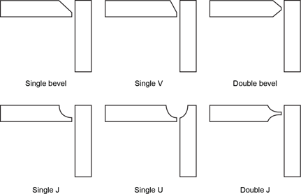
Although square corner joints are relatively easy to prepare and assemble, the variations using the bevel, the J and the U preparations require more skill and time to accurately fit the joint.
Corner joints are not satisfactory for heavy stress loading, particularly if welded from only one side. They are not normally used in construction, especially where the tension from bending is concentrated at the root of the weld. For some applications, corner joints may also be welded from the inside to increase their strength, a procedure that significantly increases the cost of the weld.
Edge Joints
Edge or flange joints are most commonly used on light-gauge material such as sheet metal. The edges of the sheet metal are turned up in a device called a brake. The turned-up edges reduce the danger of burn through on thin materials and at the same time help to prevent distortion. On thin materials, no additional filler metal is required. If selected for plate, the edges must be prepared with one of the variations shown in Figure 14 in order to ensure sufficient penetration.
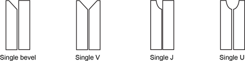
Butt Joints
Butt joints are the most widely used of the five designs. Like tee joints, butt joints provide maximum accessibility for welding. They use a minimum of weld material and, with 100% penetration, they are effective for all types of stresses. They are the preferred joint for resisting fatigue stresses if complete penetration is assured. The strength of correctly prepared and welded butt joints compares very favourably with the strength of the parent metal.
On thin metal, complete penetration and full strength can be achieved using a square butt joint without extensive edge preparation. On thicker metal, edge preparation becomes increasingly extensive. Two basic designs are used (Figure 16), the bevel and the J. These edge preparations result in eight butt joint variations.
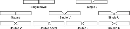
When joints are prepared and welded from both sides, they are called double joints. When welded from only one side, they are called single joints. To ensure complete penetration, a backing strip or plate is often required.
The drawbacks of the butt joint are primarily in the skill and accuracy required of the welder in fitting and welding the joint. Of the five joints, the butt joint is the most difficult to master. These joints require considerable experience to become proficient in preparing and welding because they often require extra time for back gouging or extra material for backing.
Welding Positions
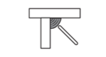
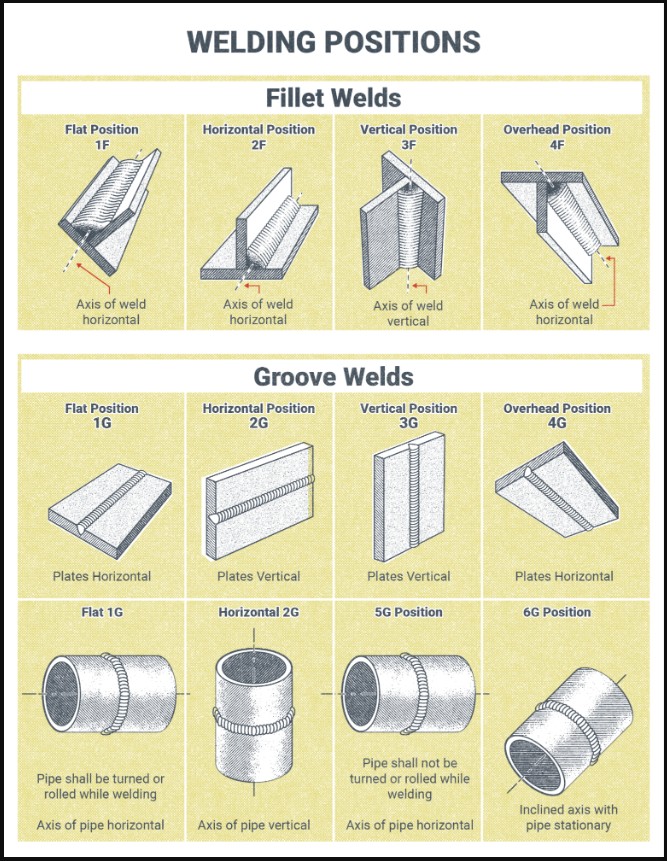
There are four basic welding positions: flat, horizontal, vertical and overhead. Welding techniques for the four positions vary according to the ease of depositing the metal. Welding in the flat position is generally faster and less tiring than the other three positions and, whenever possible, you should try to place your workpiece in the flat position.
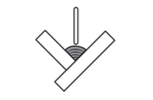
The term “position welding” refers to welding in the flat position. The term “welding out of position” refers to welding in any of the other three positions. Table 1 and Figure 17 show the four positions that are used.
| Position of Weld | Groove | Tee-joint Fillet |
| Flat | 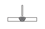 |
 |
| Horizontal | 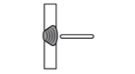 |
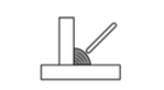 |
| Vertical | 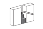 |
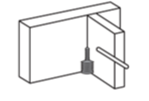 |
| Overhead | 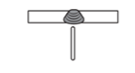 |
 |
Flat Position
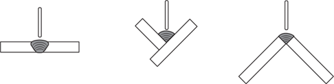
In the flat position, the workpiece is positioned so that the joint is parallel to the floor and the electrode generally points downward. For butt joints on plate, the two pieces are simply placed on a flat surface. For lap and tee joints the two pieces of plate must be supported in an angled position so that the actual joint is parallel to the floor (Figure 18). With corner joints, the ends of the plate are positioned on a flat surface so that the two pieces meet at the top to form a small tent.
Horizontal Position
Welds in the horizontal position are also parallel to the floor, but they are done along a vertical surface. Weld metal is deposited from the upper side of the joint. For butt joints, the electrode is held horizontally (parallel to the floor), but for the other four joints, it is usually either slightly higher or lower than horizontal, depending on the technique used. For butt joints, the two plates are supported in the vertical position, but the lap, tee and edge joints can be set up and welded on a flat surface. With horizontal welds, the main difficulty is that gravity causes the molten puddle to drip from the lower side of the weld.
Vertical Position
In the vertical position, the plate to be welded is positioned vertically and the weld itself is vertical. The direction of travel may be up or down, but the majority of vertical welding is usually done from bottom to top. The electrode points slightly upward. As with horizontal welding, gravity causes the molten metal to pull away from the edges of the bead and, unless the weld puddle is correctly controlled, molten metal will drip.
Overhead Position
The overhead position is the reverse of the flat position in that the weld is done from the underside of the plate with the electrode pointing upward rather than downward. Overhead welding is considered the most difficult to master. In the overhead position, the force of gravity pulls the molten metal from the toe of the weld bead to the centre of the bead where it can drip or form icicles.
Abbreviations for Weld Position and Weld Type
Abbreviations can be used to indicate the type of weld and the welding position. A fillet weld is often abbreviated to an F, and a groove weld to a G.
Each weld position is designated with a number as follows:
- Flat position (1)
- Horizontal position (2)
- Vertical position (3)
- Overhead position (4)
For example, 1G indicates a groove weld in the flat position; 3F indicates a fillet weld in the vertical position, and 4G would indicate a groove weld in the overhead position.
Additional Demonstration Videos and Resources
The following videos provide additional demonstrations of common weld types and joint configurations. These resources are intended to reinforce the concepts introduced in this section and to help you visualize proper welding techniques, positioning, and weld profiles in practice.
- Fillet Welds (Tee / Lap / Corner Joints): Welding SMAW – How to weld a fillet [10:49] by IMAT (2019)
- Groove Weld (Butt Joint): Welding SMAW – How to weld a flat V-groove[17:13] by IMAT (2019)
- Fillet + Groove Practice (Combined Context): Tacking up practice welds for fillet and groove welds. Excellent practice exercise. [7:15] by Mark Prosser Welds (2019)
- SMAW Fillet Weld (More Technical / Reinforcement): ARCademy: Fillet Welds SMAW [9:52] by American Welding Society (2021)
 Self-Test B-6.2: Identify Types of Welds, Positions, Joints and Symbols
Complete Self-Test 6.2 and check your answers.
If you are using a printed copy, please find Self-Test A-6.2 and Answer Key in the Appendix at the end. If you prefer, you can scan the QR code with your digital device to go directly to the interactive Self-Test.

References
BC Industry Training Authority. (2019). Piping trades apprenticeship program: Use Tools and Equipment—Level 1 harmonized [Binder]. Crown Publications, Queen’s Printer for British Columbia. https://www.crownpub.bc.ca/Product/Details/7960000261_S
Industry Training Authority. (2019). Piping trades apprenticeship program: Level 1—Competency B-5: Use welding equipment (Steamfitter). Crown Publications, Queen’s Printer for British Columbia.
Industry Training Authority. (2019). Piping trades apprenticeship program: Level 1—Competency B-5: Use cutting, brazing and soldering equipment (Plumber). Crown Publications, Queen’s Printer for British Columbia.
Industry Training Authority. (2019). Piping trades apprenticeship program: Level 1—Competency B-6: Use oxy-fuel cutting equipment (Plumber). Crown Publications, Queen’s Printer for British Columbia.
Industry Training Authority. (2019). Piping trades apprenticeship program: Level 1—Competency B-6: Use soldering and brazing equipment (Steamfitter). Crown Publications, Queen’s Printer for British Columbia.
Industry Training Authority. (2019). Piping trades apprenticeship program: Level 1—Competency B-7: Use oxy-fuel equipment (Steamfitter). Crown Publications, Queen’s Printer for British Columbia.
Industry Training Authority. (2019). Piping trades apprenticeship program: Level 1—Competency B-7: Use welding equipment (Plumber). Crown Publications, Queen’s Printer for British Columbia.
Rupik, D., Colameco, D., Kjeldgaard, C., Ridge, D., Oostman, S., & Fulton, K. (n.d.). Introduction to welding. Washington State Board for Community and Technical Colleges. https://openwa.pressbooks.pub/welding1/
Media Attributions
All figures are sourced from Industry Training Authority (2019) and/or Camosun College (2019) and are used under the Creative Commons Attribution 4.0 (CC BY 4.0) licence unless otherwise noted. Images copyrighted by the BC Industry Training Authority are licensed under a Creative Commons Attribution-NonCommercial-ShareAlike 4.0 (CC BY-NC-SA 4.0) licence.
- Figure 10 Basic Joint Types (Figure 15.1) by Cameron Kjeldgaard, for WA Open ProfTech, © SBCTC, is used under a CC BY 4.0 license.
- Figure 17 Open vs. Closed Root (Figure 15.4) by Nicholas Malara, for WA Open ProfTech, © SBCTC, is used under a CC BY 4.0 license.
A single-pass weld used to build up or repair the surface of metal. (Section B-6.2)
A process of adding a layer of weld material to the surface of a metal to rebuild worn areas or to increase resistance to wear and damage. (Section B-6.2)
A short weld used to hold parts in place during fit-up before final welding. (Section B-6.2)
A weld used to join two pieces of metal at right angles, forming a triangular cross-section. (Section B-6.2)
A weld that fills the gap between two pieces of metal, typically used in butt joints. (Section B-6.2)
The gap between two pieces of metal at the joint, which allows weld metal to penetrate and fuse the pieces together. (Section B-6.2)
The flat surface at the edge of a joint that remains uncut to support the weld and control penetration. (Section B-6.2)
The curved surface at the base of a joint preparation (such as a U-groove) that helps control weld penetration and allows smoother flow of weld metal. (Section B-6.2)
The point or area where two or more pieces of metal are joined together by welding. (Section B-6.2)
A tee joint in which the edges of the materials are not beveled or prepared, allowing the pieces to meet at a right angle without additional edge preparation. (Section B-6.2)
A joint that joins two pieces of metal by overlapping one piece over the other and welding along the edges of the overlap. (Section B-6.2)
A joint that joins two pieces of metal at right angles at their ends, forming an L shape. (Section B-6.2)
connections where the edges of two metal pieces are bent (flanged) and then welded together. This type of joint is often used for thin metal and helps create a neat, sealed edge. (Section B-6.2)
A joint that joins two pieces of metal in the same plane, typically by welding along their adjoining edges. (Section B-6.2)
Connections where two welds are made on both sides of the same joint to make it stronger and more secure. This helps the metal pieces hold together better and handle more stress. (Section B-6.2)
A joint that is welded from one side only, where the weld is applied to one side of the materials being joined. (Section B-6.2)
When a person welds metal pieces together while working in different positions, such as flat, sideways, overhead, or vertical. The position changes how easy or difficult the welding is and how the melted metal flows. (Section B-6.2)