B-6.4 Use Arc Welding Equipment
Achieving welds of high quality involves skill and concentration, which you will only develop through considerable practice. Consider the following five factors before each weld:
- Operator comfort and position
- Machine setting
- Arc length
- Electrode angle
- Speed of travel
Operator Comfort and Position
It is easier to weld if you are in a comfortable position and if you have a clear view of the area in front and behind the electrode. Most welders find that by placing their arms correctly, they can maintain control of the arc yet remain comfortable
If you are right-handed, grasp your right wrist with your left hand and place your left elbow on the welding bench. Use your left elbow as a pivot while you move the electrode along the metal. The usual direction for flat position welding for right-handed welders is from left to right. If you are left-handed, your arm positions and weld direction will be reversed.
Machine Setting
Before each weld using DC current, you must check that the polarity setting (either straight or reverse) is correct for the type of electrode you are using. With AC current, you have no choice of polarity, since the circuit is alternately positive, first on one side and then on the other.
You must also make sure that the current or amperage is correctly set for the electrode you are using, the type of joint, the weld position, the type of material to be welded, and the speed required for the weld. The current setting determines the welding temperature that will affect the quality and soundness of the weld.
Arc Length
The arc length (the distance of the electrode from the workpiece) is usually determined by the diameter of the electrode, with consideration to the welding position and the required amount of current. When the arc length is correct, the arc makes a distinct crackling sound. When it is too long, the crackling changes to a hissing sound.
Welding arcs that are too long prevent good penetration and fusion, permit the absorption of oxygen and nitrogen into the weld, and produce excessive weld spatter. In addition, they increase the possibility of arc blow.
Electrode Angle
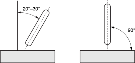
Generally, the electrode should be held perpendicular to the base metal and then inclined 20° to 30° in the direction of travel (Figure 1). For some welds, however, the electrode angle is required to remain upright, perpendicular (90°) to the workpiece.
The correct angle is important in preventing undercut and slag inclusions. It also makes it easier for you to deposit weld metal and to achieve complete penetration and fusion.
Speed of Travel
Generally, the speed of travel should be such that 25 mm (1″) of electrode produces 25 mm (1″) of deposit. This speed is only an average and may need to be increased or decreased, depending on the welding position and the heaviness of the deposit required.
Weld Faults
There are three categories of weld defects:
- Dimensional faults vary from the specifications and requirements of the weld, including incorrect weld sizes and profiles
- Structural discontinuities, including such defects as porosity, undercut, incomplete penetration, and lack of fusion
- Defects in the mechanical properties of the metal, including reduced tensile strength, ductility, hardness or corrosion resistance
Defects in mechanical properties are not a factor that you can control.
Dimensional Defects
Incorrect Weld Size
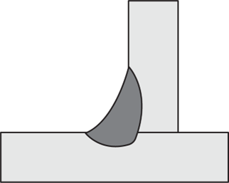
Any variation from the specified weld size influences the distribution of stress in the weld. This will affect the strength of the weld. Welds that are undersized usually have insufficient throat (Figure 2), which substantially reduces the strength of the weld. Stresses concentrate at the centre of the weld, increasing the likelihood of joint failure. Undersized welds are usually the result of a fast rate of travel.
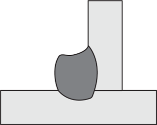
Oversized welds display excessive convexity on fillet welds and excessive reinforcement on groove welds (Figure 3). These defects tend to produce notches at the toe of the weld where stresses will concentrate. The metal also tends to entrap slag and gases, creating a condition called porosity, which undermines the strength of the weld. Inadequate fusion of the weld and parent metal is also associated with excessive convexity or reinforcement.
Overlap
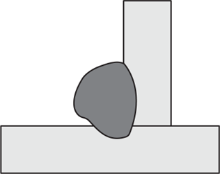
Overlap is a condition in which excess weld metal is deposited at the toe of the weld. It is most often a sign of poor fusion between the weld and parent metal (Figure 4). This condition is extremely serious, as stresses concentrate in notches that form at the toes of the weld. In fillet welds, overlap may also reduce the size of the weld.
Dimensional defects also include the distortion and warping that occur as a result of stresses from heating and cooling the metal during welding.
Structural Discontinuities in the Weld
Structural discontinuity incorporates a broad range of weld defects that include:
- Undercut
- Porosity
- Incomplete penetration
- Slag and gaseous inclusions
- Lack of fusion
- Cracking
While these defects often accompany other defects associated with size and profile problems, they may also occur in welds that conform to size and profile specifications.
Undercut
Undercut refers to a cutting away of the plate surfaces at the edge of the weld (Figure 5). A sharp recess forms in the plate where the next layer or bead must fuse with the parent metal. At this point, plate thickness is reduced, weakening the joint. The possibility of joint failure is particularly high when the undercut occurs at the toe of the weld.
Undercut is generally caused by improper electrode manipulation, but too much current, too long an arc, or slow travel can also be contributing factors. On joints that are not very accessible, undercut may be very difficult to avoid.
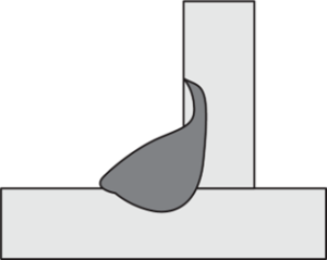
Undercut can be corrected. When it occurs at the sidewall of the weld between passes, extra metal can be deposited in the recess before the next bead is deposited. At the surface of the weld where the defect of the weld is visible, additional metal can be used to fill up the recess.
Incomplete Penetration
Incomplete penetration is the failure of the weld metal and the base metal to fuse together at the root of the joint. On groove and fillet welds, this defect occurs when the areas above the root reach temperatures before the root. The molten metal forms a bridge across the joint and prevents the arc from reaching the root.
Incomplete penetration is most often caused by a joint design that is not suitable for the welding process selected. For single groove welds, this defect is most likely the result of one of the conditions shown in Figure 6 .
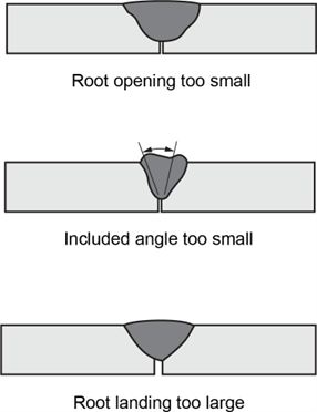
Even when the joint is correctly designed, incomplete penetration may be caused by welding procedures. With a current that is too low, the weld metal is not able to reach the root of the joint or the arc is not strong enough to melt the base metal at the root. If the rate of travel is too fast, the metal is deposited on only the surfaces above the root. Electrode size is also an important factor, especially on the root bead. If the electrode is too large, it will not penetrate the narrow root opening.
Lack of Fusion
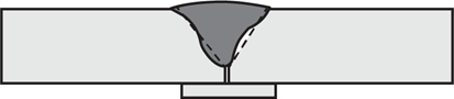
Lack of fusion is the failure of the welding process to fuse adjacent layers of weld metal or adjacent weld metal and base metal (Figure 7). This failure may occur at any point in groove and fillet welds. Overlap at the toe of the weld is often a sign of inadequate fusion.
Lack of fusion usually results from the following conditions:
- failure to heat the base metal or the previously deposited weld metal to the melting point, which usually occurs if the electrode is too small, the travel is too fast, or the current is too low
- failure to dissolve, by correct fluxing, the oxides or other foreign material on the surfaces to be welded
Porosity
Porosity refers to the presence of voids in the weld that do not contain any weld metal (Figure 8). Porosity may be distributed uniformly throughout the weld or may be clustered. Although excessive porosity has a serious effect on the mechanical properties of the joint, some welding codes allow for a specified maximum amount of porosity.
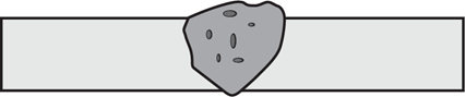
When pockets are concentrated at the root, they are often referred to as wormholes or piping. This condition is regarded as a special case of incomplete penetration.
Porosity results from the inclusion of gases in the weld. These gases are formed by the chemical reactions that take place in the weld as the metal is heated and cooled. Porosity generally occurs as a result of one of the following factors:
- Overheating or under-heating the weld metal
- Excessive sulphur or moisture in the base metal or electrode
- Current too high or too low
- Incorrect electrode manipulation
- Oil or other contaminants on the joint
- Defective or unsuitable electrodes
- Too long an arc
- Arc blow
Slag Inclusion
Slag refers to the metallic oxides and other solid compounds that are produced by chemical reactions during the welding process. Sometimes slag can become trapped in the weld. Like gaseous inclusions, they create porosity in the weld metal (Figure 9).
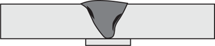
In metal arc welding, slag formation occurs particularly when using coated electrodes or fluxes. The stirring action of the arc can force the slag into the molten metal or it can be pushed ahead of the arc and then be covered over by the weld metal. Because it is less dense than molten metal, slag tends to rise to the surface of the puddle, where it can be chipped away when the weld is cooled.
Several factors can prevent the release of slag from the weld metal, including:
- High viscosity of the weld metal
- Rapid cooling
- Too low a temperature
- Incorrect manipulation of the electrode
- Undercut on previous passes
Slag inclusions can generally be prevented by preparing the weld correctly before each bead is deposited, making sure to correct the contour so that the arc can penetrate the joint completely and making sure all slag is cleaned from the surface of the previous bead. You can help to promote the release of slag by ensuring that the weld metal becomes hot enough to reduce its viscosity (thickness) and by pre- and post-heating to slow down the cooling process.
Cracking
Cracks are considered the most dangerous weld defects. They occur because of stresses that exceed the ultimate strength of the metal. Cracking that occurs shortly after the weld metal has been deposited and is just beginning to solidify is termed “hot cracking.” Some metals, especially the high alloy steels and other high-temperature alloys, are particularly susceptible to hot cracking. Cracking that occurs later, as the metal is approaching room temperature or after the weld has cooled completely is termed “cold cracking.” Cold cracking is much less common than hot cracking.
External Cracks
Cracking that is visible or external usually occurs in the weld metal (Figure 10). External cracks may run across the face of the metal and sometimes extend into the base metal. These are known as transverse cracks. Longitudinal cracks run lengthways along the weld, usually down the centre of the weld deposit. Crater cracks form in the centre of the crater and may become a starting point for longitudinal cracking. Crater cracks are usually the result of interruptions in the welding procedure.

External cracks most often are caused by too much restraint on the joint, too rapid cooling (particularly on hardenable and brittle metals), too little deposit on weld passes, and by incorrect electrode selection. External cracks may also be caused by other defects such as porosity, lack of penetration, slag inclusion and incomplete fusion. By increasing the thickness of the deposit on the first bead, decreasing the speed of travel to allow more weld metal to build up, and correcting pre- and post-heat treatments, most cracking can be avoided.
Internal Cracks
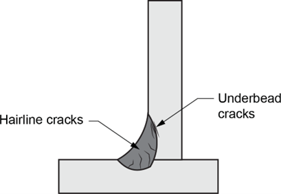
Internal cracks usually occur within the heat-affected zone of the base metal (Figure 11). Underbead cracking (a type of internal crack) occurs almost exclusively in steel and is associated with the use of low-hydrogen electrodes. Hairline cracks at the toe of the weld are caused by hot cracking in (or near) the fusion zone of weld and base metal.
Internal cracks are found chiefly in metals that have been hardened and that are fairly brittle. They are often associated with other weld faults such as undercutting, lack of fusion, incomplete penetration and slag inclusions.
Internal cracking can be prevented by the use of low-hydrogen electrodes, correct pre- and post- heating procedures, and careful attention to correct fit-up and welding procedures.
Distortion and Stress
One of the primary welding problems is the control of distortion and residual stresses that can occur in metal as it is heated and cooled during the welding process. Distortion refers to a change in shape of the weld, while residual stress refers to the buildup of internal stresses within either the weld or parent metal. Excessive distortion may result in a weld that exceeds dimensional tolerances, while excessive stress may cause weld cracking.
The underlying cause of both conditions is the characteristic of metals to expand (become larger) when heated and to contract (become smaller) when cooled. If metals are allowed to expand and contract freely (with no restraint) neither distortion nor residual stress is likely to occur. If the metal is restrained in a way that prevents free expansion and contraction (as is the case with weldments), distortion and the buildup of internal stresses can develop.
An example of this can be seen in the butt joints shown in Figure 12. When heat is applied to the joint, the metal in the weld area expands but is restrained by the surrounding cooler metal. The heated metal must expand upward in the unrestrained direction. Upon cooling, this displaced metal contracts, pulling in the surrounding metal across the width. This pulling force causes the edges of the weldment to bow upward, resulting in distortion.
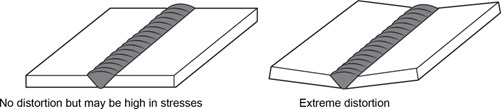
If, however, the edges of the weldment had been rigidly restrained to prevent movement, there would be little evidence of distortion, but the likelihood of residual stresses would be very high.
The susceptibility of a metal to distortion depends on its mechanical and physical properties. High- alloy steels are more prone to distortion than mild steels, and larger welds generally undergo more distortion than smaller welds.
Distortion Control
Methods used to minimize or eliminate distortion include:
- avoid over-welding
- deposit the greatest amount of weld metal in the shortest time
- distribute the heat input as uniformly as possible
- use mechanical methods
- preheat and post-heat when necessary
Avoid Over-Welding
Use the smallest permissible size on fillet welds and, where possible, use intermittent rather than continuous welds. On butt joints, select a joint design that uses a minimum of weld metal. A U-joint preparation is preferable to a vee preparation (Figure 13). If a single vee preparation is required, bevel to achieve the smallest permissible included angle.

Deposit the Greatest Amount of Weld Metal in the Shortest Time
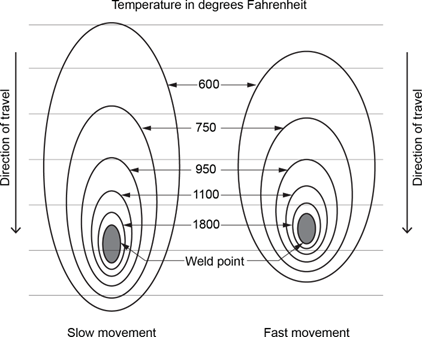
The slower the rate of welding, the more time there will be for the heat to spread ahead of the welding point. This diffusion of heat input greatly increases the chances of distortions, so a high rate of travel is usually recommended on joints that are susceptible to distortion.
Wherever possible, try to weld in the flat position and use electrodes as large as possible for the particular joint. Iron powder electrodes are particularly good as they have a high deposition rate.
On multi-pass welds, apply as few passes as possible to complete the joint. Many small passes cause more distortion than a few large passes. This is particularly true for welds that may be subject to transverse shrinkage. For welds prone to longitudinal distortion, the reverse is often the case, and the correct technique is to use multiple passes, each having a small deposit.
Distribute Heat Input as Uniformly as Possible
The rate of heating and cooling varies within the joint depending on how close the metal is to the point of welding. Expansion and contraction will not be uniform, further complicating the incidence of distortion. Behind the welding point, the metal is cooling and contracting. In front, the metal is heating and expanding. By maintaining a high rate of travel, the differences in heat input can be minimized, as shown in Figure 14.
Other techniques to keep the heat input as uniform as possible include intermittent welding sequences, back-step sequences, skip sequences, and the starting of a weld at a distance from the end of the joint. These methods break up the weld into short sections and help to control distortion and the buildup of residual stresses. The principle is that the shrinkage set up by one weld is counteracted by the shrinkage forces in subsequent welds.
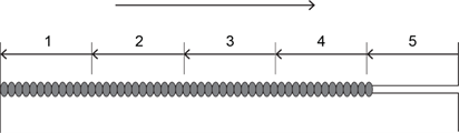
In the back step sequence, the weld begins a short distance from the end, with the direction of travel toward that end (Figure 15). The second deposit is then begun the same distance in from the first deposit and runs into the first deposit. The third deposit runs into the second and so on along the seam.
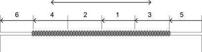
With skip welding, weld deposits are applied incrementally on each side of the centre of the seam. The first weld is made at the beginning of the joint. A section is skipped, and the second weld is applied further down the seam. Sometimes the weld starts at the centre and the weld builds back from the centre, alternating from end to end (Figure 16).
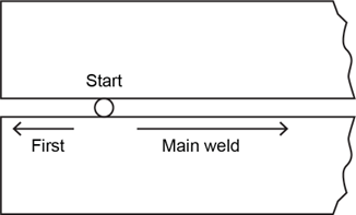
On long seams, starting the weld a short distance in from the end controls longitudinal distortion. The first weld is applied back toward the end of the joint, then the main weld picks up from the starting point of the first weld and continues to the other end (Figure 17).
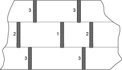
On large sections of plating, the weld should begin at a central point and proceed outward, as shown in Figure 18. The aim is to maintain a welding sequence that is more or less symmetrical around the centre.
Use Mechanical Methods
A variety of mechanical methods can minimize distortion including pre-bending, clamping and pre-spacing.
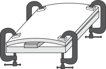
A weldment can be pre-bent and restrained through the use of clamps to compensate for warping in the other direction (Figure 19). Once the clamps are removed, shrinkage forces will pull the plate back to the desired alignment. The clamps must be spaced and aligned carefully to avoid the buildup of internal stresses.
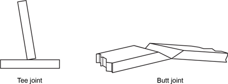
Figure 20 shows the pre-spacing or offsetting of parts to be welded. Pre-spacing, like pre-bending, compensates for the distortion that will occur when the completed joint shrinks. As shrinking occurs, the vertical member on the tee joint will be pulled into correct (90°) alignment. Likewise, the two members of the butt joint will also be drawn upward to become properly aligned.
Pre-Heat and Post-Heat When Necessary
Pre- and post-heat techniques play an important part in controlling the buildup of internal stresses and distortion.
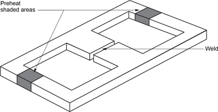
Preheating helps to distribute the expansion of the metal evenly throughout the weldment. Entire sections of the weldment may require preheating or, in some cases, preheating may be necessary only on specific sections (Figure 21). Preheating techniques require considerable care to ensure that heat is distributed uniformly throughout the metal and the structure is allowed to cool slowly.
Post-heating relieves residual stresses after the weld is completed. Heat treatments become increasingly important as you weld alloy steel, cast iron and other non-ferrous metals.
 Self-Test B-6.4: Use Arc Welding Equipment
Complete Self-Test 6.4 and check your answers.
If you are using a printed copy, please find Self-Test A-6.4 and Answer Key in the Appendix at the end. If you prefer, you can scan the QR code with your digital device to go directly to the interactive Self-Test.

References
BC Industry Training Authority. (2019). Piping trades apprenticeship program: Use Tools and Equipment—Level 1 harmonized [Binder]. Crown Publications, Queen’s Printer for British Columbia. https://www.crownpub.bc.ca/Product/Details/7960000261_S
Industry Training Authority. (2019). Piping trades apprenticeship program: Level 1—Competency B-5: Use welding equipment (Steamfitter). Crown Publications, Queen’s Printer for British Columbia.
Industry Training Authority. (2019). Piping trades apprenticeship program: Level 1—Competency B-5: Use cutting, brazing and soldering equipment (Plumber). Crown Publications, Queen’s Printer for British Columbia.
Industry Training Authority. (2019). Piping trades apprenticeship program: Level 1—Competency B-6: Use oxy-fuel cutting equipment (Plumber). Crown Publications, Queen’s Printer for British Columbia.
Industry Training Authority. (2019). Piping trades apprenticeship program: Level 1—Competency B-6: Use soldering and brazing equipment (Steamfitter). Crown Publications, Queen’s Printer for British Columbia.
Industry Training Authority. (2019). Piping trades apprenticeship program: Level 1—Competency B-7: Use oxy-fuel equipment (Steamfitter). Crown Publications, Queen’s Printer for British Columbia.
Industry Training Authority. (2019). Piping trades apprenticeship program: Level 1—Competency B-7: Use welding equipment (Plumber). Crown Publications, Queen’s Printer for British Columbia.
Media Attributions
All figures are sourced from Industry Training Authority (2019) and/or Camosun College (2019) and are used under the Creative Commons Attribution 4.0 (CC BY 4.0) licence unless otherwise noted. Images copyrighted by the BC Industry Training Authority are licensed under a Creative Commons Attribution-NonCommercial-ShareAlike 4.0 (CC BY-NC-SA 4.0) licence.
The distance between the welding electrode and the metal being welded. (Section B-6.4)
The direction or tilt of the electrode when it is held during welding. (Section B-6.4)
How fast the welder moves the electrode along the metal while welding. (Section B-6.4)
Problems with a weld where the size or shape is different from what the design requires. (Section B-6.4)
Extra weld metal that spills over the edge of a weld without properly joining to the base metal. (Section B-6.4)
Flaws or breaks in a weld that weaken the metal. (Section B-6.4)
A groove or dip along the edge of a weld that makes the joint weaker. (Section B-6.4)
A welding problem where the weld metal does not fully reach or join the bottom of the joint. (Section B-6.4)
A welding defect where melted metal does not properly join to the metal beside it. (Section B-6.4)
Small holes or bubbles in a weld caused by trapped gas. (Section B-6.4)
Pieces of solid material (slag) that become trapped inside the weld. (Section B-6.4)
Breaks or splits that form in a weld or metal because of stress. (Section B-6.4)
Cracks that form in the weld metal while it is still very hot and starting to cool. (Section B-6.4)
A change in the shape of metal caused by heating and cooling during welding. (Section B-6.4)
Stress that remains inside metal after it has been heated and cooled. (Section B-6.4)