B-2.3 Describe Stationary Power Tools Used in the Pipe Trades
Stationary power tools are used in the piping trades for fabrication and production of material used for installation, alteration and repair of systems. Commonly, many of these tools will be found on larger construction projects and in fabrication shops.
Metal Cutting Band Saw
Metal cutting band saws are available in a variety of models and sizes.
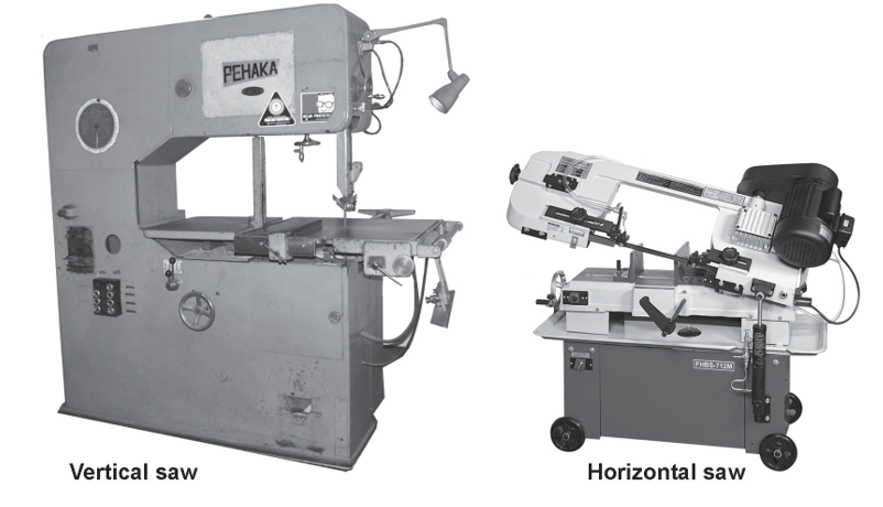
The size of the metal-cutting band saw is designated by the thickness of stock it can cut. Standard sizes are 115 mm, 180 mm, and 255 mm (4 [latex]\frac{1}{2}[/latex] in., 7 in. and 10 in.). Some larger models are capable of cutting through a pipe that is 50 cm (20 in.) in diameter. A built-in vise holds the material being cut. The vise can be rotated to allow a range of cutting angles.
These saws produce an accurate cut without an excessive buildup of heat. Some saws are equipped with a mist spray cooling system that cools and lubricates the saw blade.
The smaller models regulate the amount of cutting pressure by use of an adjustable counterweight. Larger models use a hydraulic system to regulate the feed pressure. All models are designed to shut off once the workpiece is cut. These features allow the saws to be left unattended during long cutting operations. If several smaller pieces need to be cut, they can be cut simultaneously, providing they can all be secured in the vise.
The speed of the saw blade can be reduced to prevent heat buildup during a heavy cut. Speeds may range between 21 m/min (65’/min) to 90 m/min (300’/min).
Wear the appropriate safety equipment with all cutting machines including safety glasses and a face shield, which will protect your eyes from small particles of metal that can be sent flying during the operation.
Metal-Cutting Blades
Metal-cutting band saw blades are defined by their grades of steel, tooth formation, tooth set and blade width. Grades of steel include;
- Carbon
- Semi-high speed
- High-speed steel
Tooth formations include:
- Regular
- Hook
- Skip
Carbon Steel
Carbon steel blades are used for general purpose cutting on a standard band saw. Blades made of carbon steel are less expensive to buy but are less durable than the other grades.
Semi-High-Speed Steel
Semi-high-speed steel blades cut 50% faster than carbon steel blades. They are harder than carbon steel but are able to withstand mechanical shocks and vibrations that would break harder, more brittle blades.
High-Speed Steel
High-speed steel blades cut better and last longer than other blades but are more expensive and more delicate than the other two grades.
Regular Tooth
Band saw blades with regular teeth are used for straight and curved cuts in most ferrous and hard non-ferrous metals. Blades with regular teeth can be considered general-purpose blades.

Hook Tooth
The hook-tooth blade is best for fast cutting of non-ferrous metals. The large rounded gullets are capable of fast chip removal and the forward slope of the tooth requires less downward pressure to cut. Thin sections of metal should not be cut with this tooth style due to the wide spacing of the teeth.

Skip Tooth
The skip tooth is very similar to the hook tooth blade, except for the fact that the skip tooth can cut ferrous metals, whereas the hook tooth can cut only softer metals. The wide spacing of the skip tooth makes the blade suitable for fast cutting of large sections of steel.

Hook- and skip-tooth types are available in pitches from 3 to 6 teeth per inch. Regular-tooth styles range from 6 to 32 teeth per inch. The number of teeth per inch affects the cutting speed of a band saw, and the size of stock it is best suited to cut. Blades with large numbers of teeth per inch are able to cut small, thin pieces of metal but are slow for cutting large sections. Blades with few teeth per inch cut faster but are too coarse for cutting thin sections of metal.
Tooth Set
Set is defined as the left-and-right positioning of the teeth to provide a wider cut than the thickness of the blade. The wide cut provides clearance for the blade within the cut, preventing binding and overheating.
There are two types of tooth sets available on metal-cutting band saws: the raker set and the wavy set.
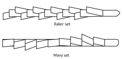
Hook- and skip-tooth blades have raker set teeth. Regular-tooth blades with up to 24 teeth per inch come with either raker set or wavy set teeth. All regular-tooth blades with more than 24 teeth per inch have wavy set teeth.
Blade Width
Band saw blades are available in widths ranging from 6 mm to 32 mm ([latex]\frac{1}{4}[/latex] in. to 1[latex]\frac{1}{4}[/latex] in.). The narrower blades are able to cut curves of a smaller radius than the wider blades. Wide blades are used for straight cuts.
Stationary Grinder
Stationary grinders may be mounted on a bench or a free-standing pedestal.
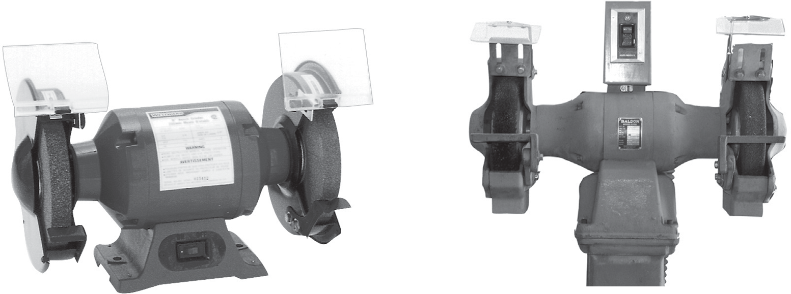
Stationary grinders consist of an electric motor with grinding or wire wheels attached to both ends of the motor shaft. The wheels are enclosed in guards that support a tool rest at the front and a spark shield. The wheels rotate so that they travel toward the operator from the top of the wheel.
Tool Rest
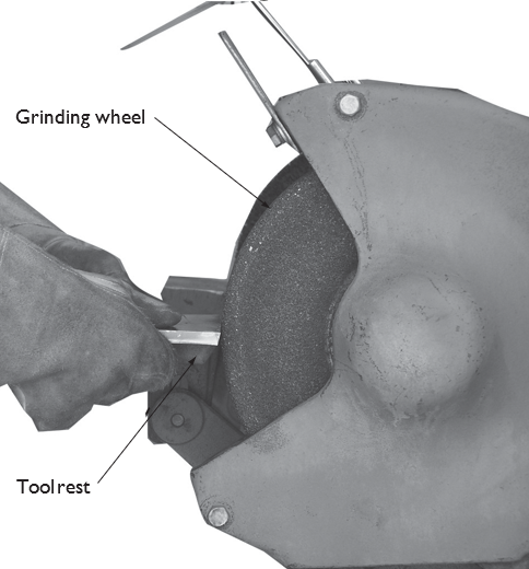
The tool rest is adjustable and must be positioned no lower than the centre of the wheel. The distance between the front edge of the wheel and the tool rest must not be more than 3 mm (1⁄8 in.).
Spark Guard
Sparks are created during the grinding of ferrous metals or when using the wire wheel. To reduce the number of sparks that hit the operator, a spark guard is mounted at the upper end of the exposed portion of the wheel. The spark guard should be mounted as close as possible to the surface of the wheel. During wire wheel brushing, grit, dust and wires may be thrown off. The spark guard reduces operator risk from flying debris. A spark guard is not a substitute for a face shield. A face shield must also be worn when sparks are expected.
Grinder Ratings
Stationary grinders have motors with different horsepower ratings. As the horsepower increases, the grinding wheels become wider and larger in diameter. Motor speeds are reduced as the diameter of the grinding wheel becomes larger.
The wheels on stationary grinders are secured between two large clamping washers or flanges held tight by a nut on the end of the spindles. The nut on the left (as seen from the front) has a left-hand thread. Removing this nut requires a clockwise rotation. The nut on the other end of the grinder has a standard right- hand thread.
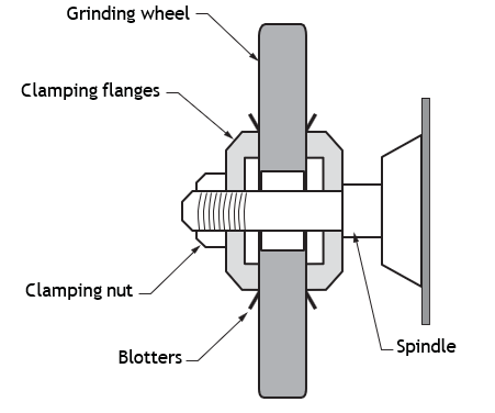
When replacing a wheel, make sure the new wheel has an RPM rating that either matches or exceeds the no-load speed of the motor.
Grinding wheels are supplied with a blotter-type paper disk on each side. The disks serve to cushion the strain caused by the flanges when the clamping nut is tightened.
Grinding wheels with hair-line cracks are unsafe and must be discarded. To test for cracks, simply stand the wheel on edge and tap the sides with a hard object, such as a screwdriver handle. Cracked grinding wheels will give off a dull sound, while a good wheel will give off a ringing sound.
Power Drives and Accessories
Power drives (also called power vises) rotate pipe so that hand tools can be used for cutting, reaming and threading operations. They are also used to drive tools that groove or thread pipe. The drive centres, holds, and rotates the workpiece as the various operations are performed.
A Forward-Off-Reverse switch selects the desired direction of rotation. To change the rotation of a vise in operation, turn the switch to the off position and wait for the machine to stop completely before flipping the switch to the opposite position.
Power vises may be mounted on a bench or on a three- or four-legged stand, depending on the type of vise and the work conditions.
Power vises, like the Ridgid Model 300 power drive, are widely used in the piping industry. This machine is designed to accept a carriage of power-driven accessories, as well as for use with hand tools.
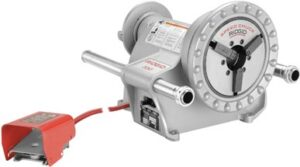
Accessories for the Model 300 Power Drive
With mounted accessories, the Model 300 power drive can serve as a threading machine. The die head, cutter, and reamer are positioned on a carriage, which slides onto support bars.
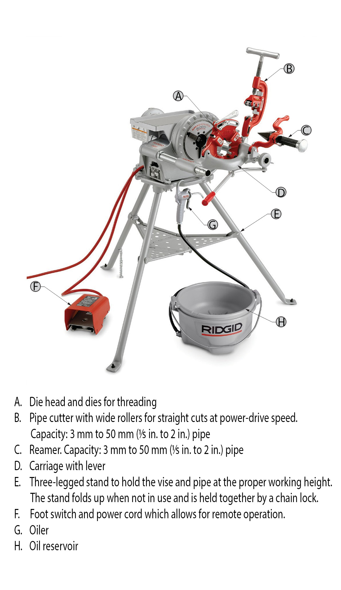
The oiler is used for applying thread-cutting oil to produce accurate, smooth threads and keep dies cooled and lubricated.
The oiler includes a hand-operated pump, a hose, and a reservoir containing a screen and chip pan. It is used only during the threading operation.
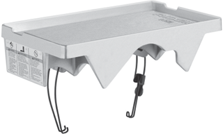
The clip-on tool tray is designed to hold hand tools while working with the power drive.
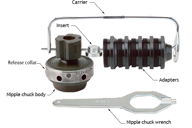
The nipple chuck (Figure 12) holds nipples or studs for threading when the vise jaws may damage the threads or when they are too short to be held in the vise. The chuck releases them easily when threading is complete.
The telescoping universal jointed drive shaft, when used with a power vise, can drive a geared threader. The pipe must be secured in a separate stationary vise. The drive shaft length can be extended from 104 cm (41 in.) to 127 cm (50 in.).

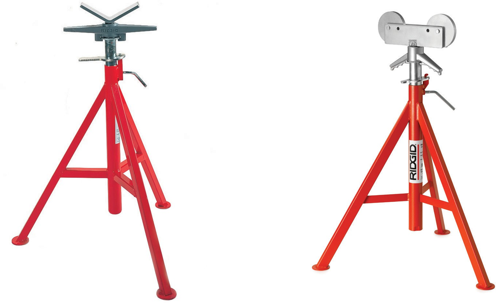
Figure 14 shows two types of adjustable pipe supports. Right-angle rollers in one style let pipe turn freely. The capacity is 10 in. pipe. Pipe supports can also be made on-site from scrap pipe, threaded rod and channel iron.
Stationary Threading Machines
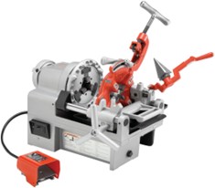
The threading machine differs from a portable power drive in that the cutter, the reamer, the carriage for the die head, and the pump to circulate thread cutting oil are built-in parts of the machine, not optional attachments. All machines are operated by a foot switch.
The threading machine is a portable machine that has the power and capacity to cut, ream, and thread large diameter pipe and conduit from 13 mm to 10 cm ([latex]\frac{1}{2}[/latex] in. to 4 in.). They can be bench mounted or fitted to a stand.
As an example, the Ridgid No. 535 pipe and bolt threading machine has a hand speed chuck or auto-chuck (to hold pipe without slipping), and the pipe can be inserted from the front or the back. Like other power threading machines, this model has tools that operate independently and swing up and out of the way when not in use. A variety of dies and die heads are available for the No. 535. A reversible pump re-circulates thread cutting oil making them a self-oiling threader. Some machines have die heads with oil passages built right into the head.
The machines can be bench mounted or fitted to an open leg or wheeled stand. Pipe capacity for the Model 535 is 13 mm to 50 mm ([latex]\frac{1}{2}[/latex] in. to 2 in.).
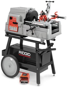
The Ridgid Model 1224 threading machine threads 6 mm to 50 mm ([latex]\frac{1}{4}[/latex] in. to 2 in.) pipe at 36 RPM and 6 cm to 10 cm (2[latex]\frac{1}{2}[/latex] in.to 4 in.) pipe at 12 RPM.
Due to their larger capacity, machines like these are ideal equipment for large construction sites and pipe fabrication shops.
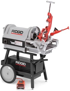
Compact styles of threading machines have also been developed for the pipe trades industries that are well suited to light duty and service work, typically for pipe up to 25 mm (1 in.) in diameter. Most can be mounted on roll-away folding stands or simply placed on a bench or tailgate for quick threading at the jobsite. Some threaders have even been developed to use an oil-free solvent to cool the dies when threading, providing for cleaner fabrication where required.
Stationary Grooving Equipment
Through the use of special equipment, piping can be smoothly and uniformly grooved for mechanical couplings and fittings. As with power threading operations, an adjustable pipe support will often be required when using grooving attachments.
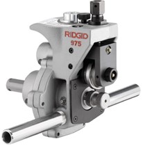
The Ridgid Model 975 combo roll groover uses rollers to form grooves in standard and thin-wall pipe. It can be combined with a power drive for machine grooving jobs, but it is also designed to manually groove pipe in-place. The 975 also comes with a permanently fixed depth setting gauge for quick setup.
Designed for quick, multiple field work, groovers like the Ridgid Model 916 are designed to be driven only by some type of power drive. Groovers like these use a single-stroke feed mechanism that allows for quick operation and minimal effort. These units have capacities of 15 cm (6 in.) diameter for copper and light wall steel, and 8 cm (3 in.) for schedule 40 steel pipe.
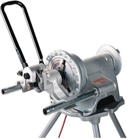
Also intended to be driven by a power vise, the Model 918 is an example of a heavy-duty hydraulic groover designed for light wall pipe up to 30 cm (12 in.) in diameter, and schedule 40 steel up to 20 cm (8 in.). The 15 tons of force exerted at the forming wheels allows for precision grooving.
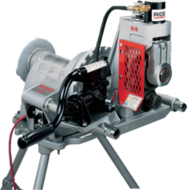
It has an extra set of support legs for additional stability and a built-in pressure gauge for accurate control of hydraulic pressure while grooving. With one of the largest capacities available, it can handle light wall pipe up to 60 cm (24 in.) and Schedule 40 pipe as large as 30 cm (12 in.).
The Ridgid 920 roll groover is a larger version of the 918 hydraulic machines, but like other groovers discussed in this section it still requires the use of a power drive to provide the muscle.
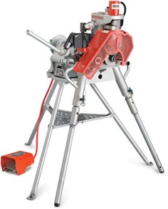
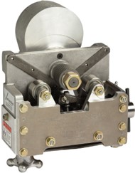
External mounting and drive action can provide quick, accurate cutting and grooving of ductile iron pipe and heavy-walled carbon steel pipe. Cut grooving removes less material from the wall of a pipe than threading does, and allows for some pipe separation and deflection.
Drill Press
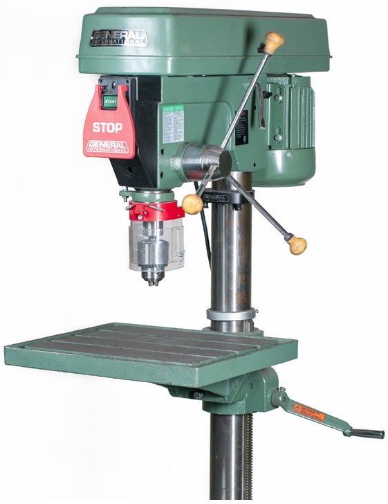
The drill press is one of the most practical power tools because of its versatility and ease of operation. A drill press can be floor or bench mounted.
Construction
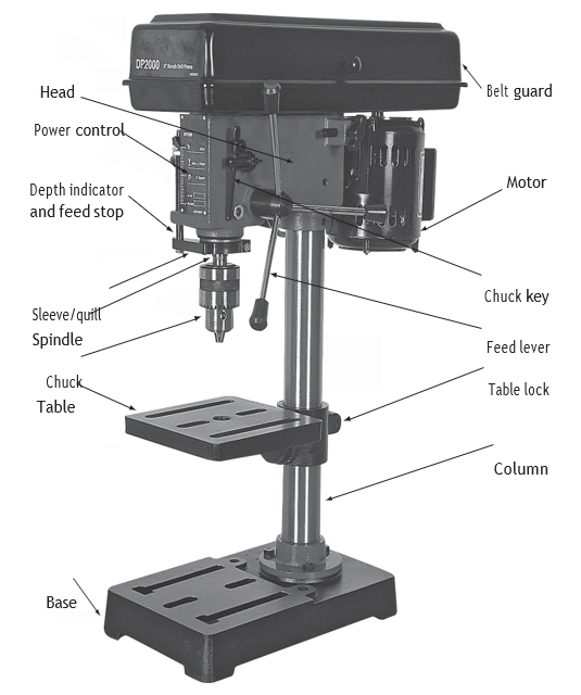
The four basic parts of the drill press are the base, column, table and head. The head is the entire working mechanism attached to the upper end of the column. The table can be moved up and down on the column. On some models, the table can be swung to either side or tilted.
The chuck is moved downward by means of simple rack-and-pinion gearing worked by the feed lever. The feed lever is returned to its normal position by means of a coil spring. You can lock the feed and pre-set the depth to which it can travel.
Power and Speed
The drill press is fitted with pulleys or gears so that different speeds can be obtained. The average drill press can obtain speeds of 680, 1250, 2400 and 4600 RPM. When the machine is used exclusively for metal work, a larger cone pulley is used on the spindle to give lower speeds of about 470, 780, 1300 and 1950 RPM.
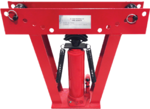
Stationary Pipe Benders
Mechanical bending is a metal forming process used to permanently change the shape of pipe or tube.
Procedures like “ram bending” or “rotary draw bending” are used to form the workpiece into the shape of a die. Straight tube stock can be formed using a bending machine to create a variety of single or multiple bends and to shape the pipe or tube into the desired form.
One side effect of bending the workpiece is that the wall thickness changes; the wall along the inner radius of the tube becomes thicker, and the outer wall becomes thinner. To overcome this, the tube may be supported internally or externally to preserve the cross section. Depending on the bend angle, wall thickness and bending process, the inside wall of the bend may crease.
 Self-Test B-2.3: Describe Stationary Power Tools Used in the Pipe Trades
Complete Self-Test 2.3 and check your answers.
If you are using a printed copy, please find Self-Test A-2.3 and Answer Key in the Appendix at the end. If you prefer, you can scan the QR code with your digital device to go directly to the interactive Self-Test.

References
BC Industry Training Authority. (2019). Piping trades apprenticeship program: Use Tools and Equipment—Level 1 harmonized [Binder]. Crown Publications, Queen’s Printer for British Columbia. https://www.crownpub.bc.ca/Product/Details/7960000261_S
Camosun College. (2019). Line C: Tools and Equipment—Competency C-2: Describe Common Power Tools and Their Uses (Rev. ed.) [Learning guide]. BCcampus. https://collection.bccampus.ca/textbook/zAYtfTec/
Camosun College. (2015). Trades Access Common Core Competency C-2: Describe Common Power Tools and Their Uses. Victoria, B.C.: Crown Publications. Download for free from the B.C. Open Textbook Collection (https://open.bccampus.ca/browse-ourcollection/find-open-textbooks/).
Media Attributions
All figures are sourced from Industry Training Authority (2019) and/or Camosun College (2019) and are used under the Creative Commons Attribution 4.0 (CC BY 4.0) licence unless otherwise noted. Images copyrighted by the BC Industry Training Authority are licensed under a Creative Commons Attribution-NonCommercial-ShareAlike 4.0 (CC BY-NC-SA 4.0) licence.
RIDGID tool images are used with permission from Emerson Professional Tools. Some of these images may have been carried forward from SkilledTradesBC learning resources; however, permission has been obtained directly from Emerson Professional Tools for their use here.
A saw blade made from carbon steel that is strong and flexible, often used for cutting wood or soft metals. (Section B-2.1)
A saw blade made from steel that is harder than carbon steel and can handle faster cutting speeds. (Section B-2.1)
A saw blade made from a special steel that stays strong and sharp even at high cutting speeds and temperatures. (Section B-2.1)
A band-saw tooth pattern with evenly spaced teeth designed for smooth cutting. (Section B-2.1)
A band saw blade with teeth that lean forward to cut quickly and remove material efficiently. (Section B-2.1)
A band-saw blade with widely spaced teeth that helps clear sawdust and is useful for cutting softer materials. (Section B-2.1)
An adjustable support on a grinder that holds the workpiece steady while grinding so the operator can control the tool safely and accurately. (Section B-2.3)
A protective shield mounted near a grinding wheel that helps deflect sparks, dust, and debris away from the operator during grinding. (Section B-2.3)
A stationary machine that rotates pipe so tools can be used to cut, ream, thread, or groove the pipe more easily. (Section B-2.3)
A device used to apply cutting oil to pipe threads or cutting tools to reduce heat, improve cutting performance, and help produce smooth, accurate threads. (Section B-2.3)
A special chuck used on a threading machine to hold short pieces of pipe (nipples) securely while they are being threaded. (Section B-2.3)
A tool or machine used to form a groove around the end of a pipe so that mechanical couplings or fittings can be attached securely. (Section B-2.3)
A stationary machine that holds and drives a drill bit vertically into a workpiece to make accurate holes. (Section B-2.3)
A process that uses a machine or tool to permanently bend pipe or tubing into a desired shape without cutting it. (Section B-2.3)
A pipe-bending method where a hydraulic ram pushes the pipe against a forming die to create a bend. (Section B-2.3)
A pipe-bending method where the pipe is clamped to a rotating die and pulled around it to form a smooth, accurate bend. (Section B-2.3)