B-2.4 Use Stationary Power Tools
Stationary Grinding Tools
Before starting a grinder, check the condition of the grinding wheel. Place a fixed reference object on the tool rest so that it just touches the face of the wheel, then turn the wheel by hand. The wheel should just contact the object at all times as it makes a full turn. If not, the wheel is out-of-round. Out-of-round wheels cause the workpiece to vibrate during grinding.
Check the condition of the face of the grinding wheel. If it shows excess signs of metal particles, it will need to be cleaned. Grinding wheels with a surface embedded with metal (Figure 1) tend to generate heat rather than to grind. The left image of Figure 1 shows dulled grains and particles of metal embedded in the wheel, while the right image shows a sharp cutting and unclogged grain surface.
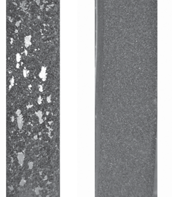
To remedy out-of-round or dirty wheels, use a wheel dresser on the face of the stone. Where the grinder design permits, the tool rest must be backed away from the grinding wheel enough to allow the dresser to hook over the front edge of the tool rest. While the grinder is running, the handle of the dresser is raised until the sectional washers touch the wheel’s face and the dresser is moved across the width of the grinding wheel. Turn off the grinder. When the grinding wheels have stopped turning, check the entire face for metal particles or out-of-round. Repeat dressing as necessary.

Remember to re-position the tool rest no further than 3 mm ([latex]\frac{1}{8}[/latex] in.) from the wheel after dressing.
When you are using a stationary grinder, you should rest the workpiece on the tool rest and apply enough pressure against the wheel so that grinding or brushing takes place. Avoid applying so much pressure that you cause a noticeable reduction in the motor’s rotation speed.
Tools such as drill bits, screwdriver tips and cold chisels occasionally require grinding to improve their performance. You should grip such tools close to the area being ground so that you can feel any build-up of heat. If heated to the point of showing colour (yellow, purple or blue), the hardness of the tool will be affected. To prevent overheating, make sure the grinding wheel is clean, and dip the workpiece in water frequently to cool it.
The Right Wheel for the Job
Selection of the correct grinding wheel not only depends on the abrasive type, grain size, bonding material, grade, structure, size and shape but also on the grinding machine, the material to be ground and the nature of the operation. Medium-grain wheels (30 to 60 grit) are often chosen when only one metal-removing or sharpening operation is desired and the resulting surface finish is acceptable. Wheels having coarse grains (i.e. below 30 grit) work best with softer materials, where material can be removed rapidly. Many bench grinders will have one wheel with a 30 grit and another with a 60 grit.
Grinding Cold Chisels
The two areas on a cold chisel that may require grinding are the cutting edge and the end that is struck by the hammer.
Flat chisels should have a cutting edge ground to an included angle of approximately 60 and should have a slight curve to the width. The struck end should have all signs of mushrooming removed.
When using the grinding wheel, the chisel should be held at the desired angle and moved across the face of the wheel. Grind one side and then the other to form a sharp edge. The pressure applied to the chisel against the wheel should not be great enough to overheat the chisel end and draw (remove) the temper. If the temperature of the chisel end rises to a point where the metal turns blue, the temper has been lost and the end softened so that it will no longer stand up to normal use. Frequently dip the chisel end in water when grinding to keep the metal cool and to prevent overheating.
Sharpening a Twist Drill
Before you sharpen a twist drill, check the dull bit with your grinding gauge to ensure that the cutting lips are at 59° and that it has a 12° lip clearance. If it has the proper angles, these can act as a guide when you sharpen the drill tip. If the angles are not correct, you will know which areas require more grinding.
Place the twist drill so that the cutting lip to be ground is facing up and its cutting edge is level. Move the shank to your left until the axis of the drill is at 59° to the surface of the grindstone.
If the drill has a correct lip angle, the cutting edge will be exactly parallel to the surface of the stone.
Rotate the shank of the drill while sharpening so that the axis of the drill forms an angle of 12° to the horizontal.
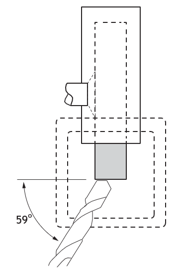
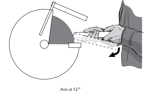
Begin sharpening the cutting lip of the drill, continuing to lower the shank end of the drill bit as the grinding proceeds. You may wish to practise this motion several times with the grinder turned off. When this “dry run” (practice motion, with the grinder off) feels right to you, rotate the drill one half turn and see if you can repeat the required angle and motions.
When doing the actual sharpening, always start the grinding at the cutting edge, and tilt the bit so that you finish at the heel. Try not to remove any more metal than is required to achieve a sharp cutting lip. Check the length of each cutting lip often to maintain equal lengths.
If both cutting lips are at the same angle (59°) and the same length, the point of the bit will be centered. If the point is not centred properly, it is because one or both of these conditions has not been met.
You must be careful not to overheat the drill bit during the grinding operation. Dip the end of the twist drill in cold water frequently to prevent excessive heat buildup. Never allow the surface of the drill to get so hot that it turns blue from the heat—the temper (hardness) of the metal will be destroyed, and the drill will no longer remain sharp during use.
Safety with Stationary Grinders
There are some rules that must be observed when using stationary grinders:
- Always wear a face shield
- Wear leather gloves and protective clothing
- Always use hearing protection
- Use both hands to control the work
- Ensure that the RPM rating of the wheel will not be exceeded
- Ensure that the wheel is suitable for the type of material
- Never reverse a wire wheel, as the wires in the wheel will have taken a “set”
- When cleaning small parts, hold them with pliers, never with your hands
- Ensure that the wheel has not been damaged
- Ensure that all guards are in place
- Ensure that the tool rest is properly adjusted
- Always stand to one side when starting the grinder
- Remove flammable materials from the work area
- Have people not involved in the grinding operation leave the area
- Never grind on the side of a grinding wheel, as this can weaken the wheel and cause it to break apart.
Be sure all grinding wheel safety devices such as wheel guards, spark deflectors, eye shields and tool rests are installed and properly adjusted before operating a grinder.
Stationary Threading and Grooving Tools
In this section you will learn safe procedures for cutting, reaming, threading and grooving using various styles of power vises and cutting machines.
Safety Precautions for Operating a Power Vise
- Know the machine. From the information in this guide and the operator’s manual, find out what the vise will do and how to operate it to accomplish that work. Know, as well, the limitations of the machine.
- Avoid accidental starting. Make sure that the machine’s Reverse/Off/ Forward switch is in the Off position and that the foot switch will operate freely. These checks must be made before the machine is connected to a power source.
- Ground the machine. The machine should be grounded while in use to protect the operator from electric shock. The machine is equipped with an approved three-conductor cord and three-prong grounding type plug to fit the proper grounding type receptacle. The green (or green and yellow) conductor in the cord is the grounding wire. Never connect this wire to a live terminal. If the unit is for use on less than 150 volts, it has a 115 V plug. If it is for use on 150 to 250 volts, it has a 230 V plug.
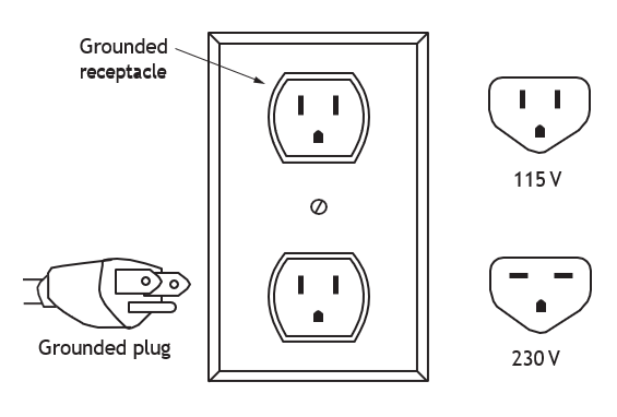
- Use only three-wire extension cords that have three-prong, grounding-type plugs and three-hole receptacles that accept the machine’s plug. Replace or repair damaged or worn cords immediately. When the machine is used outdoors, use only those extension cords that are suitable for use outdoors and are so marked.
- Remove tools from the machine. Form the habit of checking to see that the machine is clear of adjusting wrenches and other tools before starting.
- Support the work. Support long, heavy work with a floor pipe support.
- Secure the machine. Make sure that the machine is stable. A power drive must be bolted to the floor when used with a universal drive shaft.
- Do not reach across the machine. Operate the machine from the switch side only. Keep proper footing and balance. Be sure your foot can be removed safely from the foot switch at all times. Do not reach across the machine, and keep clothing, hands and tools away from moving parts.
- Maintain the machine in top condition. Use sharp cutting tools and keep the machine clean for best and safest performance. Follow lubricating instructions.
- Work in a safe environment. Do not use the machine in damp or wet locations. Do not expose the machine to rain. Keep work area well illuminated. Allow sufficient space to operate machine and accessories properly and for others to pass safely. Keep the power cord away from heat, oil and sharp edges. Make sure that hand tools that are not being used are not, in any way, obstructing machine operation.
- Disconnect the power cord. When adjusting, servicing or changing accessories, disconnect the power cord. The cord should be in top condition, and examined at regular intervals.
Safety Precautions for Operating a Model 700 Portable Power Drive
Follow the safety procedures for operating power vises modifications:
- Check the off switch. Before plugging in the power cord, push down on the switch button a couple of times to make sure that the switch button spring returns the switch to the Off position. A safety feature of this machine is that the power drive automatically stops when the operator lets go of the switch button on the handle of the machine.
- Use the proper accessories. The support arm assures safe operation when using this machine with drop head threaders in any position. The Model 700 power drive may also be used with a geared pipe threader. In that case, the power drive is not used with the support arm.
Cutting Pipe Using Power Tools
In this section, you will learn safe procedures for cutting pipe using different stationary power tools.
Inserting Pipe in a Power Vise or Threader
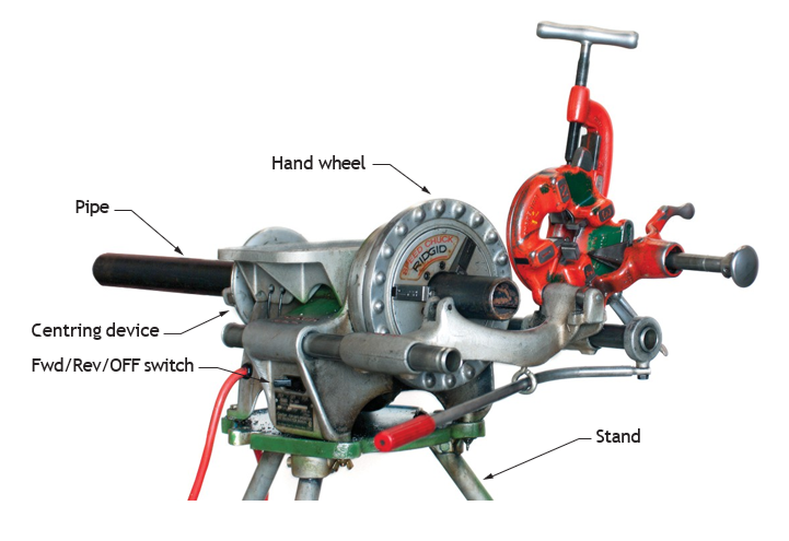
The following general procedure describes inserting pipe into power vises or threading machines:
- Measure and mark the length of pipe being worked.
- If pipe is long enough to be retained by the centring device, insert the pipe through the front or rear of the machine. If the pipe is short, insert it into the front of the machine.
- Make certain that the pipe is centred in the centring device, if used, and tighten the device.
- Tighten the chuck jaws with a repetitive counter-clockwise snap-spin of the hand wheel.
This hammering action tightens the jaws on the pipe. A clockwise rotation snap-spin releases the jaws.
Cutting Pipe with a Hand Cutter Using a Power Vise
The following general procedure describes cutting pipe using a hand cutter and power vise:
- Measure, mark, and secure the pipe in the power drive.
- Engage the pipe with the pipe cutter and align the cutter wheel with the mark on the pipe.
- Rest the pipe cutter frame on the support bar, which is located on the switch side of the machine. Tighten the feed screw (sometimes called a feedscrew) handle.
- With the power cord plugged in, turn the main switch to the forward position.
- Place foot on the foot switch to operate the machine.
- Continuously tighten the feed screw handle until the pipe cut is completed (Figure 7).
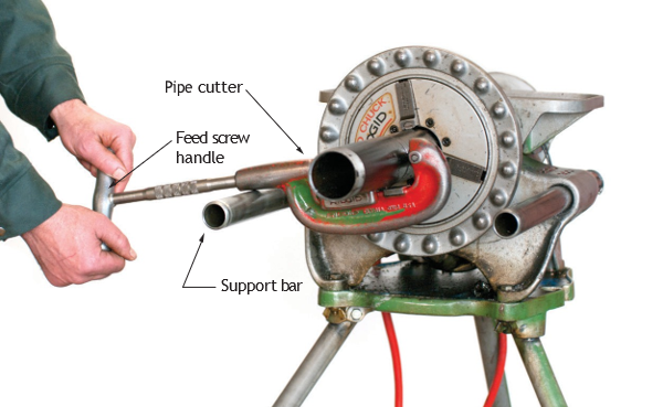
Figure 7 Cutting pipe with hand cutter (BC Industry Training Authority, 2019). CC BY-NC-SA 4.0 - Release the foot switch.
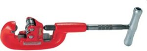
Figure 8 shows hand cutters that can be used with power drives. The heavy-duty wide roll pipe cutter is especially suited for power drive use as the wide-rolls keep the cutter from wobbling.
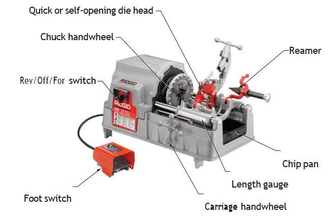
Accessories for cutting, reaming, threading and oiling can be mounted on the power vise to con- vert it into a power threader. Below is a standard power vise with cutting, reaming and threading attachments installed. On this unit, oiling must be done manually.
Cutting Pipe with a Power Vise Cutter
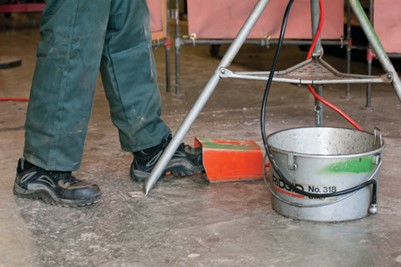
Assume the correct operating position for cutting, threading, and reaming. Stand on the switch side of the power vise, straddling the nearest tripod leg. The left foot operates the foot switch.
- Measure the pipe and mark the place where the cut is to be made.
- Swing the reamer and threader out of the way.
- Move the pipe cutter down onto the pipe.
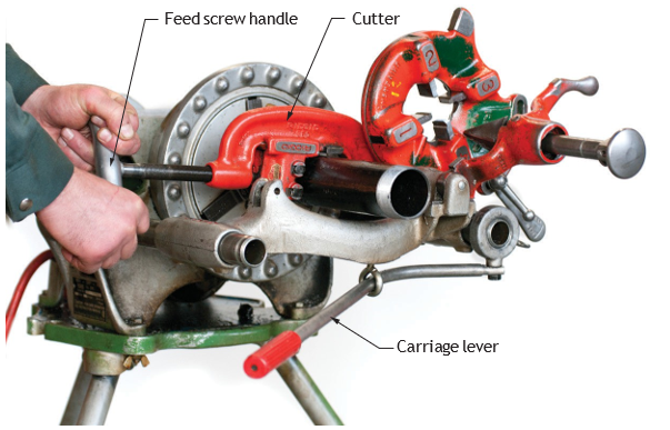
- Use the carriage lever to move the carriage to the point where the cutter wheel lines up with the mark you have made on the pipe.
- Tighten the cutter feed screw handle until the cutter wheels are snug against the pipe.
- With the main switch still in the forward position, step on the foot switch.
- Using both hands, continuously turn the cutter feed screw handle until the pipe is cut off.
- Release the foot switch.
- Return the pipe cutter to its out-of-the-way position.
Cutting Procedure Using a Power Threader
- Measure the pipe and mark the cut-off point.
- Insert the pipe into the chuck.
- With the reamer and the die head in an out-of-the-way position, bring the cutter down over the pipe, and position it on the mark you have made.
- Turn the cutter handle to cut.
To use length gauge on machine carriage, place cutter wheel against end of stock and set pointer to “0”, raise to clear stock, and turn carriage hand wheel until pointer is at length desired.
Reaming Pipe Using Power Vises or Threading Machines
In this section, you will learn safe procedures for reaming using various styles of power vises and reaming tools.
Reaming Pipe Using a Power Vise and Hand Threader
Follow the safety precautions for power vises, outlined in Safety Precautions for Operating a Power Vise.
- Check to see that the main switch is in the forward position.
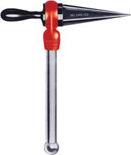
- Insert the reamer into the end of the pipe and hold firmly onto handle and handgrip (Figure 13).
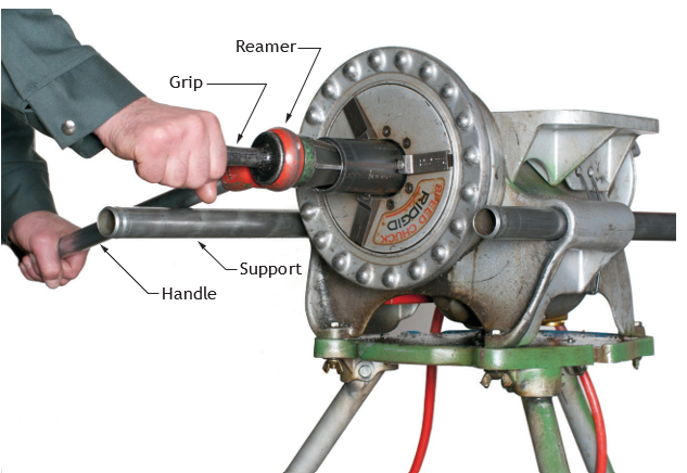
- Step on the foot switch and slowly push on reamer handgrip (same Figure 13), with right hand to ream pipe.
- Release foot switch and remove reamer.
The straight reamer is a safe hand tool for manual use with power vises. Spiral reamers are not safe.
Reaming Pipe with a Power Drive Reamer or Threading Machine
Assume the correct operating position by standing on the switch side of the power drive, straddling the tripod leg. Use left foot to operate the foot switch.
- Move the reamer arm down into the reaming position.
- Extend the reamer by pressing the latch and sliding the knob toward the pipe until the latch engages the bar.
- With the main switch in the forward position, step on the foot switch.
- Position reamer into pipe and complete reaming by pushing carriage lever. Exert pressure on the hand wheel for the same action on a power threader.
- Retract the reamer bar and return the reamer to out-of-the-way position.
- Release the foot switch.
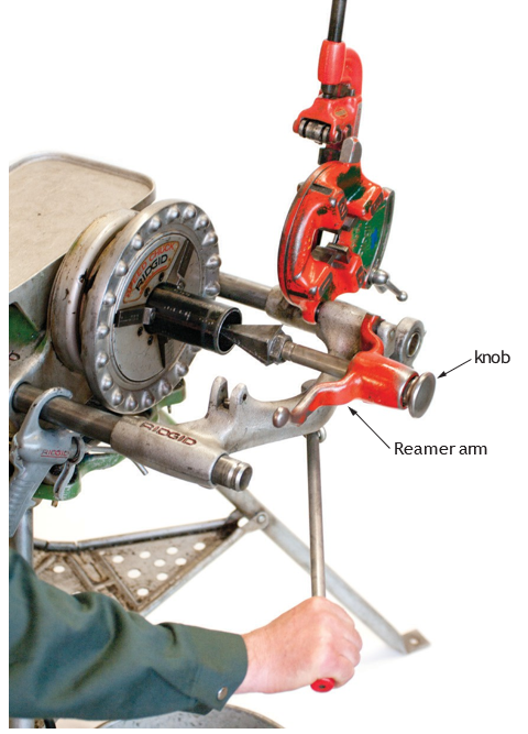
Figure 15 Reaming pipe with power drive reamer (BC Industry Training Authority, 2019). CC BY-NC-SA 4.0
Threading Pipe Using Power Vises or Threading Machines
A quick-opening die head is the standard drive mounted threading accessory. Depending on the pipe size, different die sets are installed which determine the number of threads per inch.
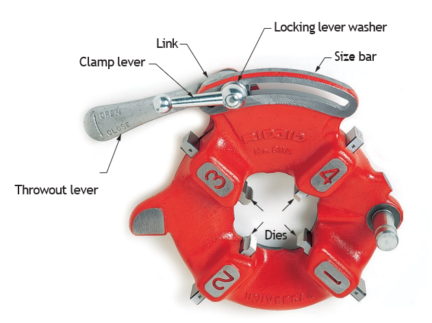
Install a Die Set
- Select the correct set of dies for the pipe size. The size is marked on either the back end or the face of the dies.
- Lay the die head on the workbench with the numbers on the head facing up.
- Flip the throw-out lever to the open position.
- Loosen the clamp lever approximately three turns.
- Lift the tongue of the locking lever washer up out of the slot under the size bar. Then slide the sizing mark all the way to the end of the slot.
- Insert the dies to the line marked on the side of the dies, numbered edge up. Note that the die numbers 1 through 4 must correspond with the numbers on the die head slots.
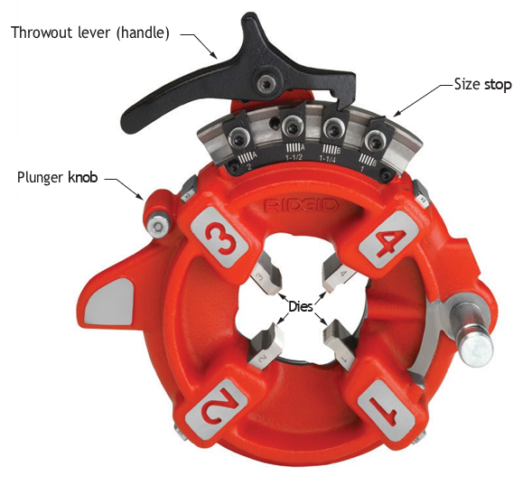
Figure 17 Semi-automatic die head (BC Industry Training Authority, 2019). CC BY-NC-SA 4.0 - Slide the throw-out lever back so that the tongue of the clamp lever washer will drop into the slot under the size bar.
Adjust the Die Head to the Size Desired
- For standard threads, adjust the size bar of the die head until the index line on the link lines up with the proper size mark on the size bar.
- Tighten the clamp lever.
Thread Pipe with Quick-Opening Die Head
- Install the die set.
- Swing the cutter and reamer to an out-of-the-way position.
- Lower the die head into the threading position.
- Apply thread cutting oil to the end of the pipe.
- Ensure that the main switch is in the forward position.
- Step on the foot switch.
- Engage the dies with the pipe, using the carriage lever.
- Use plenty of thread cutting oil until the thread is completed.
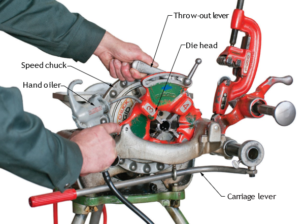
The thread is completed when the end of the pipe is flush with the numbered end of the dies.
- When the thread is completed, raise the throw-out lever to the open position.
- Move the carriage lever away from the pipe end and return the die head to the up-and-out- of-the-way position.
Using a Geared Threader
In this section you will learn safe procedures for using a geared threader.
Install the Geared Threader on a Power Vise
- Place the adjusted threader on the floor or on a workbench, with the drive shaft up.
- Install the drive bar on the drive shaft of the threader and tighten the two set screws.
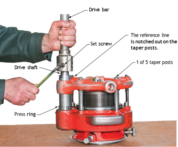
- Insert the drive bar into the chuck of the power vise. (This will likely require the assistance of another person to pick up the threader and drive bar.)
- Tighten the jaws of the power vise chuck into the three V-shaped notches in the head of the drive bar. Be sure to allow about 18 mm ([latex]\frac{3}{4} \text{"}[/latex] in.) of the drive bar to be exposed in front of the chuck jaws. This will provide space for oiling.
- Close the rear centring device on the shaft of the drive bar.
- Pull out the support bar on the switch side of the vise and secure it in the extended position.
- Slip the gear case loop over the support bar and secure it in the hole provided on the threader with the set screw.
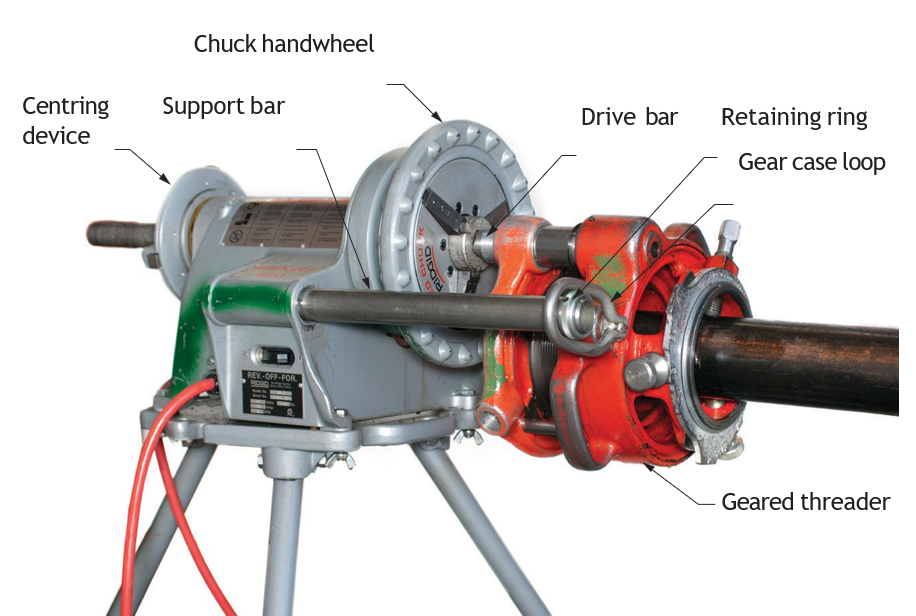
Figure 20 Geared threader close-coupled to power drive (BC Industry Training Authority, 2019). CC BY-NC-SA 4.0
Position the Pipe in the Threader
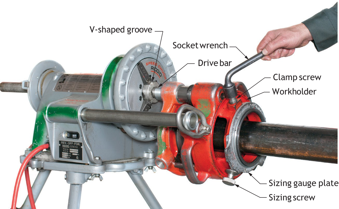
- Set the sizing screws using the gauge plate.
- Insert the pipe in the threader and centre the end of the pipe in the throat of the dies.
- Turn the work holder with a socket wrench to centre the pipe and hold it in position.
- Tighten the clamp screw, securely locking the pipe in the work holder.
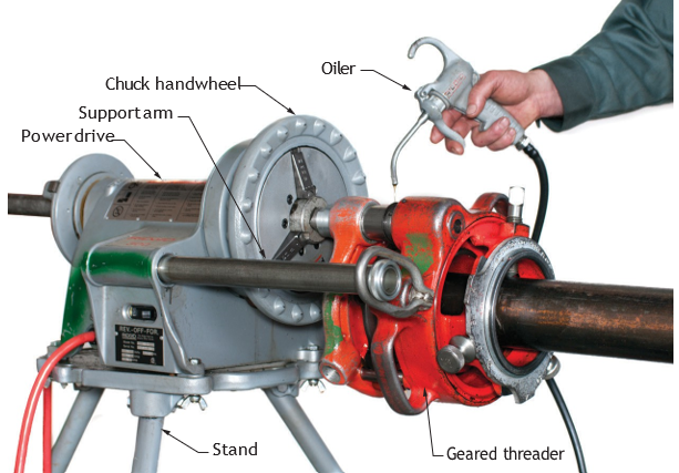
- Place the oiler directly under the threader. Long pieces of pipe must be supported by a pipe support, with the pipe free to rotate as it is threaded.
Cut Threads with a Geared Threader
- After the geared threader and pipe are installed, put in the power cord.
- Turn the power drive switch to the forward position.
- Step on the foot switch.
- Flood die with thread cutting oil during the threading operation to ensure the die’s long life.
- Release the foot switch when the red STOP line appears on the pinion sleeve (Figure 22). (The die head starts to press on the ring at the base of the pinion sleeve.)
- Turn the power drive switch to off. When motion stops, turn the switch to reverse and press the foot switch to unscrew the dies from the pipe. Loosen the set screw and the work holder from the pipe.
Using Nipple Chucks
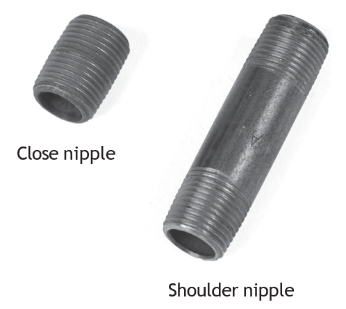
A nipple is a short piece of pipe, 300 mm (12 in.) or less in length, threaded on both ends.
The size of a nipple is designated by its diameter and length. For example, a 13 mm × 15 cm ([latex]\frac{1}{2}[/latex] in. × 6 in.) nipple is made of 13 mm pipe, 15 cm long ([latex]\frac{1}{2}[/latex] in. pipe, 6 in. long.) A close nipple has threads along its entire length. The shoulder nipple has a short section of unthreaded pipe between the threads on each end.
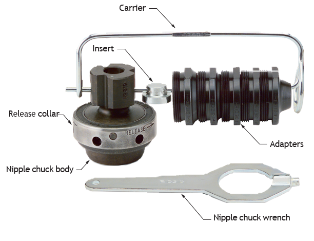
The nipple chuck is used to hold nipples (or studs) for threading when the nipple is so short that the jaws of the power vise would damage the threads. The nipple chuck is inserted into the jaws of a power vise or threader.
The nipple chuck accommodates pipe sizes up to 5 cm (2 in.). Adapters are used with 38 mm (1[latex]\frac{1}{2}[/latex] in.) pipe and the smaller sizes, according to the size of the pipe.
The nipple chuck provides a means of holding a nipple with threads on one end, while cutting, reaming, and threading the other end. It also provides an easy release so that the nipple can be removed without overcoming the binding torque applied while threading.
Procedure for Short or Close Nipple Threading with Power Threading Machine
- Ream and thread one end of the pipe in the usual manner. Cut off the end to the desired length of the nipple.
- Install the nipple chuck in the power vise so that the jaws fit into the grooves of the nipple chuck.
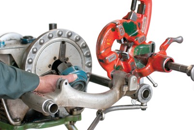
Figure 25 Installing the nipple chuck (BC Industry Training Authority, 2019). CC BY-NC-SA 4.0 - Position the insert. For pipe sizes 3 mm to 19 mm ([latex]\frac{1}{8}[/latex] in. to [latex]\frac{3}{4}[/latex] in.), the small end of the insert should face the adapter. For 25 mm (1 in.) pipe size, the large end should face the adapter. No insert is required for pipe sizes of 32 mm (1[latex]\frac{1}{4}[/latex] in.) or larger.
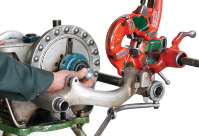
- Select the proper adapter and screw it into the nipple chuck.
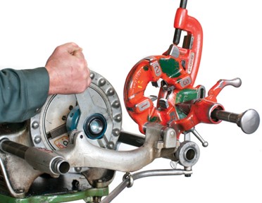
- Insert the nipple, threaded on one end, into the adapter by hand.
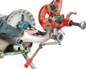
- Ream and thread the unthreaded end of the nipple.
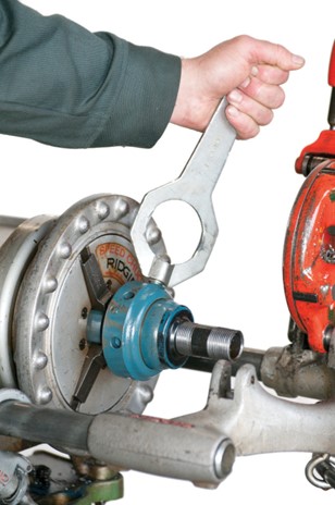
- To release the nipple, insert the pin on the end of the wrench into one of the holes on the release collar. Turn the wrench approximately a one-quarter turn in the direction indicated by the arrow to release. The nipple may be removed by hand.
Using Grooving Attachments
The roll groover forms grooves in standard pipe so that the pipe can be joined by mechanical couplings. Grooved pipe and fittings form a strong, leak-resistant conveyor for hot and cold fluids. They are easy to install and service and handle expansion and contraction without stress. They are ideal for use in heating and cooling systems, as well as in fire standpipe, sprinkler, and storm and roof drainage systems.
A grooving operation produces results similar to a threading operation. Like threading equipment, grooves can be cut with hand tools having ratchet handles, or with groove cutters or groove rollers driven by a power drive. With some grooving equipment, the pipe remains stationary during the cutting process; with other equipment, the pipe rotates between the rolls.
The Model 925 roll groover may be mounted on a stand designed for the machine, or it can be attached to a bench. A support stand is used to hold pipe longer than one metre (3 feet).
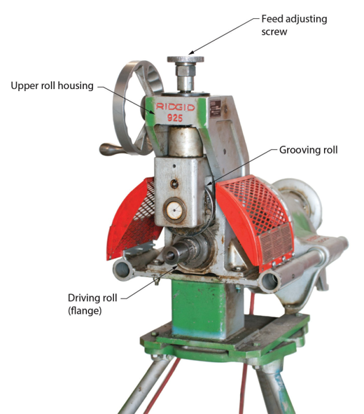
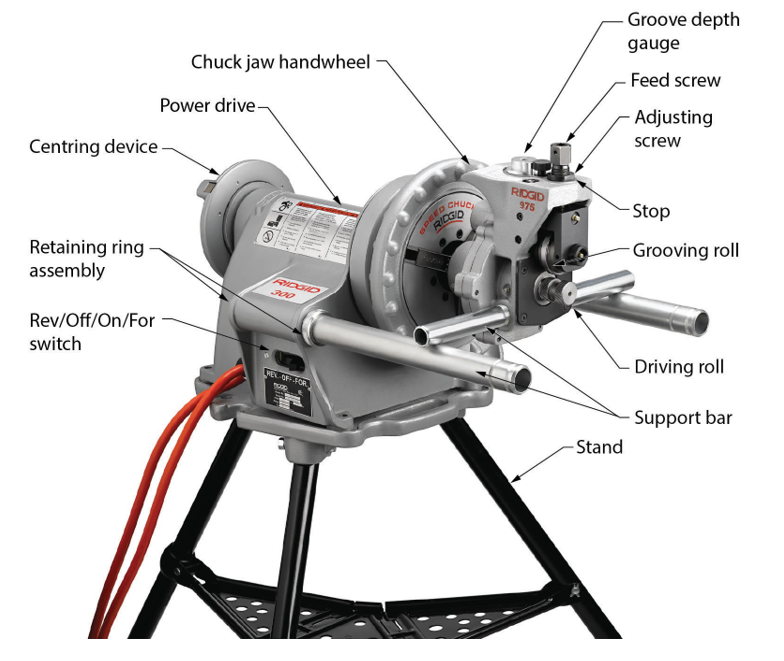
For safety reasons, the roll groover should not be operated at a speed faster than 36 rpm; and if it is mounted on a stand, the stand should be firmly anchored to the floor. The machine should be grounded and secured tightly to the power drive.
Preparing Pipe for Grooving
The following procedure is for grooving pipe with a maximum diameter of 15 cm (6 in.). It is assumed that the proper stop, grooving roll, and driving roll are already installed on the machine.
- Ensure that the pipe is cut to the correct length and the ends are square cut.
- Ensure that both the internal and external surfaces of the pipe are smooth and uniform from the end to at least 50 mm (2 in.) back. Any internal or external weld beads or seams in this section must be ground down until they are flush with the pipe wall.
- Remove burrs, coarse scale, rust and any other irregularities on the surface of the pipe with a reamer, a file, a grinder, a sander, or a wire brush. Do not create flat areas or recesses on the gasket seating surface.
Operating the 925 Roll Groover
- Ensure that a pipe length longer than 1 m. (3 ft) is supported with a pipe stand. The pipe stand, with rollers to hold the pipe level, allow it to rotate, and prevent lateral movement at a distance [latex]\frac{3}{4} \text{"}[/latex] of the pipe length away from the driving roll flange. Pipe longer than 6.5 m. (21 ft) should be supported by two stands.
- Place the pipe end on the driving roll against the flange.
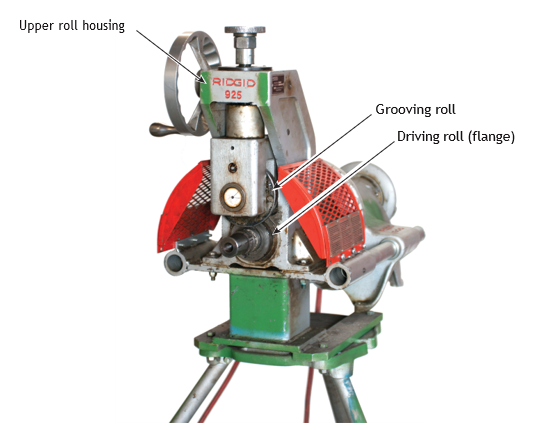
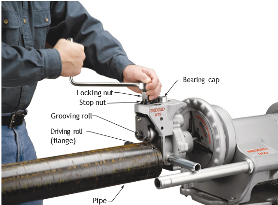
- Adjust the pipe (and pipe support stand) so that it comes in contact with the roll flange on one side only. To do this, face the groover and move the support stand holding the pipe to the right until the axis of the pipe is [latex]\frac{1}{2}[/latex]° off the axis of the driving roll (Figure 33). For example, 10 ft from the groover, the pipe should be 25 mm (1 in.) to the right of centre.
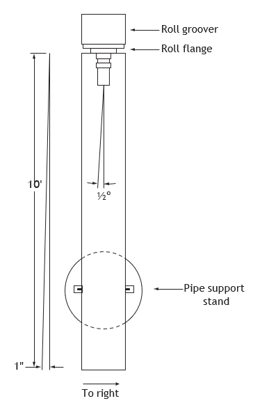
- Turn the hand wheel clockwise to bring the grooving roll in contact with the pipe.
- Turn the feed screw for grooving depth down against the upper roll housing (Figure 34).
- Back off the feed screw by the number of marks required to obtain the proper groove depth for the pipe size. For example, an 8 cm (3 in.) pipe groove should be 2 mm (0.078 in.) deep. (This is about eight hundredths of an inch back off the feed screw 8 marks.)
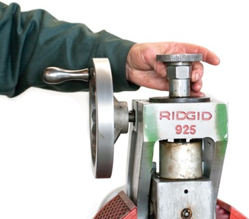
The manufacturer’s manual for operators contains a chart specifying nominal groove depths for pipe sizes. Each mark on the 925’s feed screw represents approximately 0.03 mm (0.01 inches).
- Tighten the adjusting screw against the feed screw. Make sure the feed screw does not move.
- Plug the power cord of the power vise into an electrical receptacle.
- Turn the main switch of the power vise to the forward position.
- Rotate the pipe slowly by jogging the foot switch (briefly pressing the foot switch). This will enable you to keep the pipe on the driving roll and against the flange. During the grooving operation, it is very important to keep the pipe against the flange of the driving roll. Serious injury could result if the pipe becomes disengaged from the drive shaft.
- If the pipe moves away from the flange, turn the vise switch to the Off position, and back off the grooving roll using the hand wheel. Reposition the pipe, and again use the hand wheel to engage the grooving roll with the pipe. Then repeat Steps 9 and 10.
- Continuously feed the grooving roll into the rotating pipe by turning the hand wheel clock wise.
- When the stop nut bottoms against the bearing cap, allow the pipe to make two complete revolutions before releasing the foot switch.
- Disengage the pipe and measure the diameter of the pipe groove, using an outside micrometer or a pie tape. Two readings, 90° apart, should equal the required groove diameter. (A mechanical coupling without the seal should just bottom when held completely closed in the groove.)
- If the groove is not to specifications, adjust the stop nut accordingly and continue grooving until you obtain the correct groove diameter.
Using a Drill Press
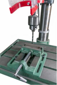
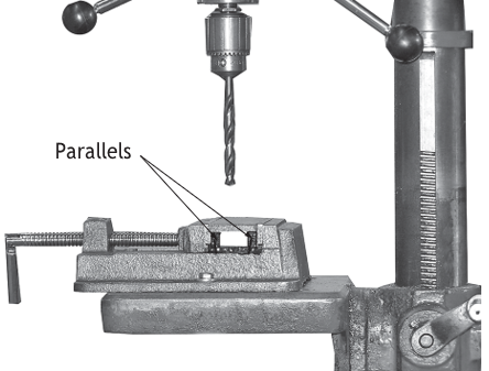
A drill bit turning in a piece of metal exerts significant torque, which tends to cause the work to rotate. The twisting action increases when the drill bit breaks through the underside of the piece being drilled. A piece of work spinning on the end of a drill can cause serious bodily injury, break the drill bit, or spoil the work. Clamping the work or mounting it to prevent twisting avoids this hazard. A machine vise (Figures 36 and 37) can be used for holding smaller items. Large pieces should be secured with C-clamps.
Speed and Feed
The speed in any drilling operation is determined by the kind of material and the size of the hole. The smaller the drill bit, the greater the required speed in RPM. The speed should also be higher for soft materials than for hard materials.
On most drill presses, it is difficult to obtain the exact recommended speed, but you can come close by adjusting the drive belt on the step-cone pulleys. You will find instructions on adjusting the pulleys in the manufacturer’s manual, or else ask your instructor to demonstrate this procedure. There is usually a chart in the manual or on a tag fixed to the machine that gives the various speed ratios for your particular drill press.
Feed is the amount of pressure you apply to control penetration. Too much pressure will force the tool beyond its cutting capacity and can result in rough cuts and jammed or broken bits. Too light a feed, particularly with metals or other hard materials, will cause overheating of the bit, and burning of the cutting edge. The best results will be obtained by matching the correct speed with a steady feed pressure that lets the bits cut easily at an even rate.
Safe Use of the Drill Press
Before proceeding with any drill press operation, you should understand the following safety pre- cautions:
- Never attempt to hold the work by hand. Use a vise or clamp to prevent the work from spinning.
- Use a face shield to protect yourself from flying chips.
- Never set speeds or adjust the work unless the machine is stopped.
- Keep away from revolving parts of a drill press to prevent your clothing from being caught.
- As the drill begins to break through the work, ease up on the drilling pressure and allow the drill to break through gradually.
- Always remove burrs from a drilled hole with a file or scraper, not with your hands.
- Never leave a chuck key in the drill chuck.
- Never attempt to grab work while the drill is still in motion; stop the machine first.
- Always position the table or the vise so that the drill bit will not damage either of them as it penetrates through the work.
- Before you start to drill, check the speed settings.
 Self-Test B-2.4: Use Stationary Power Tools
Complete Self-Test 2.4 and check your answers.
If you are using a printed copy, please find Self-Test A-2.4 and Answer Key in the Appendix at the end. If you prefer, you can scan the QR code with your digital device to go directly to the interactive Self-Test.

References
BC Industry Training Authority. (2019). Piping trades apprenticeship program: Use Tools and Equipment—Level 1 harmonized [Binder]. Crown Publications, Queen’s Printer for British Columbia. https://www.crownpub.bc.ca/Product/Details/7960000261_S
Camosun College. (2019). Line C: Tools and Equipment—Competency C-2: Describe Common Power Tools and Their Uses (Rev. ed.) [Learning guide]. BCcampus. https://collection.bccampus.ca/textbook/zAYtfTec/
Camosun College. (2015). Trades Access Common Core Competency C-2: Describe Common Power Tools and Their Uses. Victoria, B.C.: Crown Publications. Download for free from the B.C. Open Textbook Collection (https://open.bccampus.ca/browse-ourcollection/find-open-textbooks/).
Media Attributions
All figures are sourced from Industry Training Authority (2019) and/or Camosun College (2019) and are used under the Creative Commons Attribution 4.0 (CC BY 4.0) licence unless otherwise noted. Images copyrighted by the BC Industry Training Authority are licensed under a Creative Commons Attribution-NonCommercial-ShareAlike 4.0 (CC BY-NC-SA 4.0) licence.
RIDGID tool images are used with permission from Emerson Professional Tools. Some of these images may have been carried forward from SkilledTradesBC learning resources; however, permission has been obtained directly from Emerson Professional Tools for their use here.
A condition where a grinding wheel is not perfectly circular, causing vibration during use. (Section B-2.4)
A quick turning motion of a hand wheel used to tighten or loosen chuck jaws on a pipe or tool. (Section B-2.4)
The process of smoothing and slightly enlarging the inside of a hole or pipe to remove rough edges and improve fit. (Section B-2.4)
Cutting tools used to create threads on the outside of a pipe or rod so it can be connected to fittings. (Section B-2.4)
A short piece of pipe, usually threaded on both ends, used to connect two fittings or sections of pipe. (Section B-2.4)
A special chuck used on a threading machine to hold short pieces of pipe (nipples) securely while they are being threaded. (Section B-2.3)
Short rods or fasteners, often threaded on both ends, used to join or secure parts together. (Section B-2.4)
A machine that uses rollers to press a groove into the end of a pipe so it can be connected with mechanical couplings. (Section B-2.4)
A fixed piping system in a building that supplies water for firefighting, allowing hoses to be connected on different floors. (Section B-2.4)
How fast a machine or tool rotates, usually measured in revolutions per minute (RPM). (Section B-2.4)
The amount of pressure you apply to push a cutting tool into the material while drilling or grinding. (Section B-2.4)