B-1.1 Describe Hand Tools Used in the Pipe Trades
This section presents the hand tools most commonly used by pipe trades workers. Many of these tools are used during your in-school training, while others may be encountered on a job site or in a fabrication shop. While reading, pay special attention to the safety precautions required when using hand tools.
Cutting Tools
Cutting tools are used by pipe trades workers to shorten a piece of material to a desired length, or to remove part of a material from an object.
Compass and Keyhole Saws
Compass and keyhole saws have narrow, tapered blades.
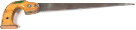
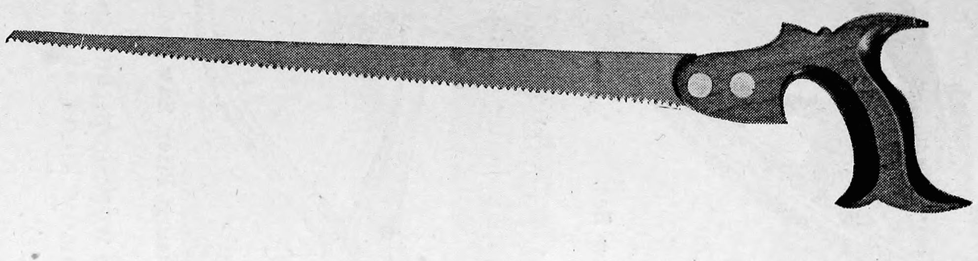
The section of blade used depends on the curve to be cut. The wide part of the blade should be used for large-radius curves and the narrow part for small cutouts. Because the blade is so narrow, care must be taken to prevent it from buckling. The blade on these saws varies in length from 250 mm (9.8 in.) to 350 mm (13.8 in.), and the teeth are filed in the same manner as the teeth on a crosscut saw.
Hacksaws
The hacksaw consists of a handle, metal frame, and saw blade. The adjustable type accommodates different sizes of blades, from 200 mm (8 in.) to 400 mm (16 in.) in length. The non-adjustable type holds only one size of blade, typically 300 mm (12 in.) in length. A hacksaw has a protective handle that helps guard your fingers in case the blade breaks or your hand slips while you are using the saw.
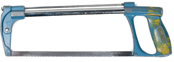
Hacksaw blades are made of hard, tempered (heat-treated) steel. The blade may be “all-hardened” or flexible. The flexible blade has only the teeth hardened, while the all-hardened blade has been tempered throughout. Since hacksaw blades are tempered, they are too hard to be resharpened. Once a blade becomes dull, it must be discarded.
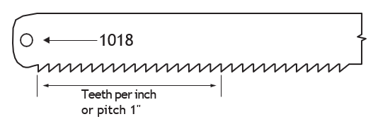
The pitch (number of teeth per inch) may be 14, 18, 24 or 32. The part number, stamped on each blade, is occasionally a code number that may indicate the blade length and number of teeth per inch. For example, code number 1018 identifies a blade 10 in. (250 mm) long with 18 teeth per inch, while code number 1032 identifies a 10 in. (250 mm) blade with 32 teeth per inch. The blade below shows that there are 18 teeth per inch and a blade length of 10 in. (25 cm).
Wood Handsaw
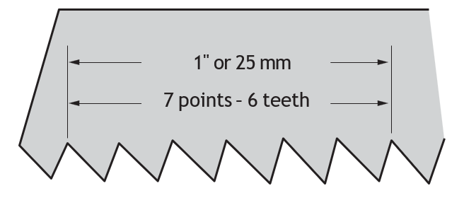
The tool most people think of as the handsaw is either a crosscut saw or a ripsaw. The crosscut saw is designed to cut across the grain of wood, and the ripsaw is designed to cut with the grain. The number of points, usually shown on the saw, indicates the number of points per 25 mm (per inch) of cutting edge.
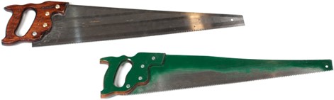
The blade of the saw is made of spring steel, tempered to provide a longer-lasting edge on the teeth after they are filed and set (offsetting of the teeth). The face of the blade is ground and polished. The smooth surface reduces friction between the saw and the wood. A handsaw of good quality has a taper-ground blade, where the back of the blade is thinner than the tooth edge. With this design, less set is required.
The set of the saw is just as important as the sharpness of the teeth, for the set is the clearance the saw blade has when it cuts wood. The width of the cut is called the kerf. The kerf is important.
Handsaws are generally specified by the shape of the teeth (i.e., crosscut or rip).
The length of the blade and the number of points per 25 mm (or per inch). The number of points (which are the valleys between the teeth) is usually stamped on the heel or printed with the manufacturer’s label on the side of the saw. Figure 6 shows a diagram of 7 points and 6 teeth in 25 mm (1 in.). The number of teeth is always one fewer than the number of points.
Crosscut Saw
The crosscut saw varies in length from 500 mm to 700 mm (20 in. to 28 in.). The points also vary from 6 to 14 per 25 mm (1 in.). The crosscut saw used for framing has fairly coarse teeth. The saw used for finishing work has finer teeth.
The framing saw is normally 700 mm (28 in.) long and has 7 or 8 points per 25 mm (1 in.). It is used mostly for cutting common lumber and making the rougher cuts for framing.
The finishing saw, also called a panel saw, is about 550 mm (22 in.) long, with 10 to 11 points. It is mostly used for making fairly precise cuts through exterior and interior trim and through panelling.
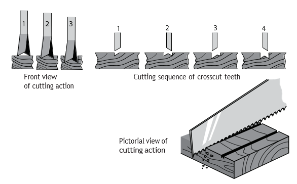
The teeth of a crosscut saw are shaped like knives to give a scoring action for cutting across the grain of wood. Most of the cutting is done on the forward stroke of the saw. The images below show the cutting action of the crosscut.
Ripsaw
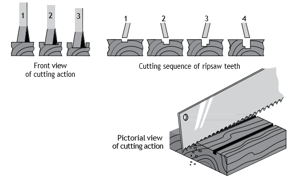
The ripsaw is designed to cut with the grain of wood. Its teeth are shaped like tiny chisels. A common ripsaw for carpenters has 5 [latex]\frac{1}{2}[/latex] points per 25 mm (1 in.) and the blade is about 700 mm (28 in.) long. Figure 8 shows its cutting action. The portable circular handsaw has made the use of the ripsaw virtually obsolete.
Files
There are many different kinds, sizes, and cuts of files available. Only the more common ones are discussed here. While files can be used for both metal and wood, in the piping trades we generally use files primarily for metal.
Files have the following general uses:
- Removing excess material
- Fitting materials together more accurately
- Correcting errors resulting from inaccurate machining (for example, threads on bolts)
- Creating a flat or smooth surface
- Forming an edge
- Creating a notch or slot
- Creating a square or round hole
The size of a file is determined by its length from point to heel; the tang is not included in this measurement.
Each part of a file has a particular name. You will need to be familiar with these names as they will be referred to in descriptions of the different kinds of files and their characteristics.

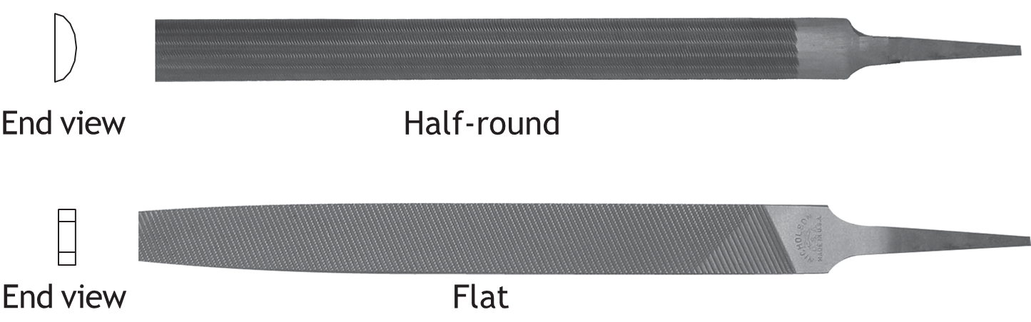
All files are classified by shape and by cutting face. The most common shapes of files are flat, round, half-round, and triangular and are used in the piping trades, primarily on metals. The flat file has teeth on both edges and is used for general-purpose filing. The round file (also known as the rat-tail file) has teeth covering the full circumference. This file is used primarily for enlarging circular openings or filing curved surfaces. The half-round file has one flat side and teeth on all surfaces. The triangular or three-square file is used to clean out corners of a square shape or to file at odd angles. All faces have teeth and the corners between the faces are left sharp.
Cutting Faces
Cutting faces are classified according to the design of the cutting and according to the grade of their teeth.
There are three designs of cutting face: the single-cut, the double-cut and the curved tooth.
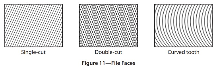
The single-cut file has one unbroken course of teeth running across the face of the file and is used when a smooth finish is desired. The double-cut file has two broken courses of teeth crossing each other. It is used for rough, fast metal cutting or where large amounts of material must be filed off. The curved tooth file is used to file soft metals such as lead or aluminum. It removes material very quickly and produces a smooth surface after each filing stroke.
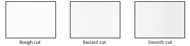
The second classification identifies the grade of the file teeth. There are six different grades for both single- or double-cut files. However, the curved tooth file is available in only three grades: the bastard cut, second cut and smooth cut.
- Rough cut
- Second cut
- Coarse cut
- Smooth cut
- Bastard cut
- Dead-smooth cut
The only difference in the grades is the spacing between the teeth. The rough-cut file has the greatest space between the teeth. As the spacing decreases, the cut becomes smoother. Remember, though, the spacing is in relation to the overall size of the file. For example, a large bastard-cut file has more space between the teeth and larger teeth than a small bastard-cut file, even though both are bastard-cut files. Figure 12 shows different grades of a single-cut file.
Hand Shears
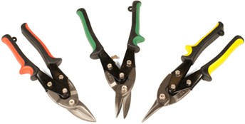
Hand shears are also called tin snips or aviation shears. They will generally cut sheet metal up to 1.5 mm ([latex]\frac{1}{16} \text{"}[/latex] in.) thick.
The construction of hand shears varies greatly; some are made to cut only straight, while others are made to cut left or right curves.
Yellow-handled snips are used for straight cuts and general purpose tin work, red-handled snips have blades that are designed for left-curved cuts, and green-handled snips are designed for right-curved cuts.
Chisels
Chisels are made of tempered steel and have a sharp beveled edge for cutting or shaping different types of material. To do so, place the sharp edge against the material and push or pound the end. The size, shape, and sharpness vary with the different types of material to be cut.
Cold Chisels
Cold chisels are forged from square, rectangular, hexagonal and octagonal high carbon steel stock and are used for metals. The steel is machined and then hardened (cold tempered). The body and head are softer than the cutting edge so that they can withstand a striking force without chipping. The upper end of a chisel has a slight taper (chamfer) to compensate for the mushrooming caused by repeated hammer blows.
Pipe trades workers generally use chisels for the removal of rusted machine parts, shearing of bolts, chipping metal and removing pins. Cold chisels are generally used for metal and not wood.

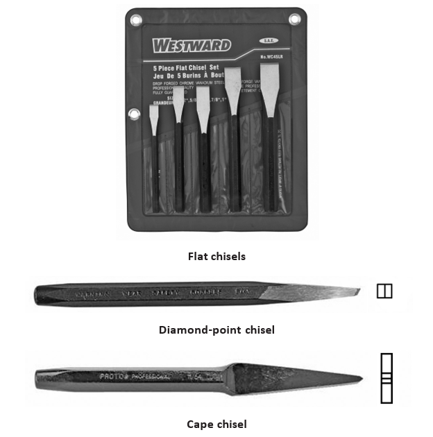
The flat cold chisel is used for most general cutting and chipping work. The cutting edge is bevelled (tapered) from both sides toward the center. The angle of the bevel is generally between 60° and 70°. For soft metals, the angle should be reduced; for very hard metals, it should be increased.
Flat cold chisels have cutting edges that vary in width from 6 mm to 25 mm ([latex]\frac{1}{4}[/latex] in. to 1 in.) and they are usually from 150 mm to 200 mm (6 in. to 8 in.) in length.
Wood Chisels
Wood chisels are classified according to length, width and thickness of the blade. They are also classified according to purpose, type, blade shape and method of holding the handle.
Types of wood chisels:
- framing chisels: the heaviest of the chisels
- finishing chisels: for lighter specific work
- gouges: a curved chisel with different blade sweeps or patterns
Framing chisels are usually used for heavy-duty type framing work, so they are referred to as such.
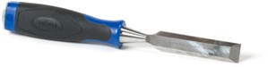
The framing chisel is made so that it can be driven with a steel hammer. The steel continues from the blade to the end of the handle, and the handle is moulded on each side of the steel. The framing chisel is the heaviest of the chisels. It varies in width from 20 mm to 50 mm and in blade length from 150 to 200 mm.
 Check Your Knowledge: Saws, Files, and Chisels
Complete the Complete the interactive knowledge test below.
If you are using a printed copy, you can scan the QR code with your digital device to go directly to the interactive knowledge test.

Pipe Cutters
Pipe cutting may be done either by hand or with power accessories. Cutters are available in a number of designs and sizes. Their use depends on the situation and on the size and material of the pipe being cut.
For any type of jointing operation, it is very important that the pipe end be cut squarely. The correctly selected cutter provides the best results, quickly and accurately. A hacksaw should never be used to cut pipe, because it’s difficult to achieve a square end. Chips from the cut may fall into the pipe and, if not removed, can cause problems with joints (especially if the piping is the type that is glued together). Chips can also contaminate the fluid that will eventually be carried through the pipe.
Most pipe cutters have a hook-shaped frame, with a cutter wheel at the end of the hook. On the stem of the hook, a sliding housing containing two rollers is mounted. These rollers hold the pipe in position against the cutter wheel. The sliding housing is moved by a long feed-screw, which is tightened as the tool is rotated around the pipe, forcing the cutter wheel into the pipe. The rollers tend to roll down the external burr that is usually raised on the pipe as the cutter wheel moves the metal. Note that these types of cutters don’t actually remove any material, but rather they spread the material into two sections. Note that wider rollers create less chance of the cutter wheel spiralling up the pipe. This provides for better cutting performance and greater accuracy when cutting pipe.
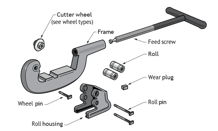
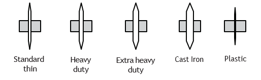
Care must be taken that the cutter wheel is appropriate for the cutter being used and is suited to the material being cut. The illustration below shows the main types of cutter wheels. The standard thin wheel is designed for cutting ordinary steel pipe; stronger, heavier wheels are for cutting heavy-walled steel pipe; and thinner wheels are used for materials like thin-walled tubing or soft materials like plastic pipe.
Before using a cutter wheel, always inspect it to make sure that it is not blunt or damaged. A blunt or dulled cutter tends to crush rather than cut the pipe. Also, ensure that no rollers and screw fasteners on the cutters are loose or missing. Misalignment or an incomplete cut could result.
Cutters may be classed as:
- Standard wheel-and-roller cutters
- 3-wheel or 4-wheel cutters (without rollers, only cutting wheels)
Heavy-Duty Pipe Cutters
These cutters can be used as single-wheel-and-roller cutters for work on heavier piping materials like steel. For cutting in confined areas, these cutters can be converted to 3-wheel cutters by replacing the two rollers with extra cutter wheels.
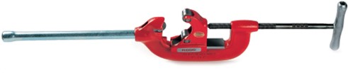
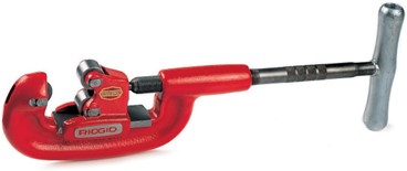
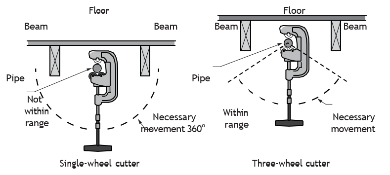
As shown in Figure 20, a 360° rotation of the wheel-and-roller cutter is necessary to cut pipe. With a three-wheel cutter, a rotation of just over 120° is all that is required. However, more care must be taken when starting a cut with the three-wheel cutter to make sure the cut is straight. These cutters can be challenging to line up correctly to achieve square cuts. The three-wheel cutter also leaves more of an outside burr, which must be removed on every cut to avoid difficulty when using threading or grooving equipment.
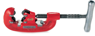
Four-Wheel Cutters
This cutter is designed for work in areas where a complete turn is not possible.
One style has a short handle for extra-tight areas where only a 130° turn can be accomplished. Pipe capacity is for this style of cutter is often 20 mm ([latex]\frac{3}{4}[/latex] in.) to 50 mm (2 in.).

Some larger options are available with the addition of a second handle, making it possible for two people to cut large pipe sizes in confined areas. Pipe capacity can easily be in the range of 6.5 cm (2[latex]\frac{1}{2}[/latex] in.) to 10 cm (4 in.).
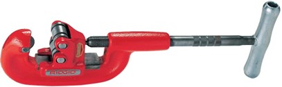
Heavy-Duty Wide Roll Cutter
This style of cutter was developed for use with a power vise. The extra wide rollers prevent the cutter from wobbling during the cutting operation, and prevent spiralling (or what is sometimes referred to as a barber’s pole). Pipe capacity is typically 3 mm ([latex]\frac{1}{8}[/latex] in.) to 50 mm (2 in.).
Hinged Cutter
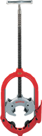
Hinged cutters are used for pipe in the ranges of 10 cm (4 in.) to 30 cm (12 in.). They can be used in tight quarters where cutter rotation is limited, like in a ditch or trench. A hinged cutter has four cutter wheels, a long handle for leverage, and a latch to engage the cutter head around the pipe. A second handle may be added for extra cutting leverage.
Soil Pipe Cutters
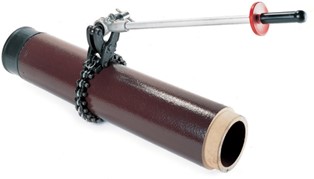
These types of non-rotational cutters (often simply called snap cutters) are designed for cutting straight lengths of cast iron soil pipe and other materials that are brittle, or easily broken. Each “wheel” is actually more like a tooth that bites into the pipe, applying even pressure at multiple points until the cutting process is achieved.
Operating the handle of the ratchet type cutters tightens the chain until the pipe is snapped by the cutting wheels between the chain links. This style has an advantage in confined quarters or when making a cut on an existing pipe that must be cut in-position.
The scissor-type cutters open and close quickly and are suited to multiple cuts in new construction work. To make the cut, squeeze the handles toward each other until the cutting wheels in the chain have completed the cut.
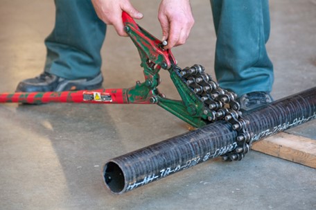
Both cutters cut 5 cm to 15 cm (2 in. to 6 in.) clay tile pipe, cast iron drainage pipe, and water mains up to 10 cm (4 in.) made from these types of brittle materials.
External Glass Pipe Cutter
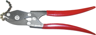
External glass pipe cutters are available as small, pocket-size tools having a chain with cutting wheels to cut glass tubing, glass pipe, and other fragile, tubular material. The chain is wrapped around the tube. Twist of the wrist and squeeze of the handles, the material is cut. Maximum pipe capacity is often 38 mm (1[latex]\frac{1}{2}[/latex] in.).
Internal Glass Pipe Cutter
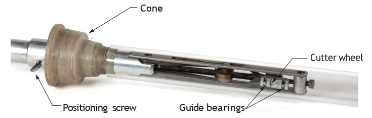
This type of cutter is used for scoring the inside of a glass pipe prior to heating and breaking it. The cutter is inserted in the pipe and the cutter wheel is set to the desired length. The cutter is rotated one full turn only and then carefully removed. The glass pipe is then heated with a small gas torch, and the pipe will break cleanly along the internally scored line. Cutters are available for pipe from 13 mm to 25 mm ([latex]\frac{1}{2}[/latex] in. to 1 in.) and from 38 mm to 150 mm (1[latex]\frac{1}{2}[/latex]in. to 6 in.).
Internal Pipe Cutter
This cutter is available in models that will cut either plastic pipe or metallic tubing.
It can be used for trimming tubing below floor level for shower, floor drain or floor flange installations, or above the ceiling for sprinkler-head installations.
Tubing Cutters
The tubing cutter is used to make clean, square cuts on copper, brass, aluminum, and thin-walled conduit. These light-weight cutters commonly have a foldaway reamer attached to them that may often have a small square hole in it to operate the valve stem of a B-size acetylene tank. Other tubing cutters will have a slide-out deburring tool with a small blade that spins as it is rotated inside the pipe.
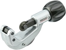
It is extremely important that tubing cutters not be used to cut pipe, as the thin cutting wheel used for tubing would be immediately damaged.
A tube is a thin-walled pipe, commonly made of copper, aluminum, brass, carbon steel, stainless steel, or plastic. Because of the thin wall, standard pipe threads cannot be formed on tubing. Instead, procedures such as soldering or brazing may be utilized. Special fittings are also available for tubing that use compression or flared connections, for example.
Close-Quarters Tubing Cutters
These miniature cutters are specifically designed for use in restricted spaces on small diameter, hard and soft copper, aluminum, brass and plastic tubing. They are designed with rollers with grooves in them. The grooves allow the cutter to make a cut close to the end of a tube that has been flared. They have common capacities of 6 mm to 29 mm ([latex]\frac{1}{4}[/latex] in. to 1 [latex]\frac{1}{8}[/latex] in.).
Plastic Tubing Cutters
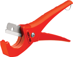
These scissor-style quick-opening cutters are designed for speedy cuts on all sorts of plastic tubing up to about 4 cm (1[latex]\frac{5}{8}[/latex] in.) outside diameter (OD). To complete a square cut, rotate the handle slightly while applying pressure.
Larger ratcheting cutters of a similar design are also available for cutting plastic tubing, or plastic pipe, up to approximately 6 cm (2[latex]\frac{3}{8}[/latex] in.) OD.
Pipe Reamers and Deburring Tools
A reamer is a precision tool used to slightly enlarge and smooth an existing hole or pipe end to a specific diameter. A deburring tool removes rough edges, burrs, or sharp fragments left after cutting, drilling, or threading. The objective is to bring the interior diameter of the pipe back to its original full bore, avoiding turbulent flow and unwanted restriction to fluid flow. Reaming and deburring can be done by hand. Certain types of reamers are designed for use on power vises. Reaming is always done before threading to avoid deforming or flaring-out the threaded end.
Straight Fluted Ratchet Reamer
This reamer works fast and clean, with light pressure. It is designed for use when pipe is to be held stationary in a vise or when the pipe is being rotated in a power vise. It is the only reamer discussed that is safe for using with a power vise.
Two models of the straight ratchet reamer are available. One has a pipe capacity of 3 mm to 2.5 cm ([latex]\frac{1}{8}[/latex] in. to 2 in.). The other has a pipe capacity of 10 mm to 8 cm ([latex]\frac{3}{8 }[/latex] in. to 3 in.).
Spiral Ratchet Reamer
This reamer is designed for hand use only. This tool is made for reaming large pipe by hand up to 10 cm (4 in.) in size. The type of work being done will dictate the size and type of reamer to be used.
Hand-held spiral reamers should not be used in conjunction with power vises because the reamer may bind into the pipe and be pulled from your hand, possibly causing a serious injury.
Deburring Tools
For light-wall tubing and soft materials like plastic pipe, other styles of deburring tools are available.
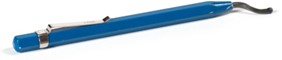
Blade-type deburring tools are ideal for removing internal burrs in copper, plastic, aluminum and steel tubing. Most types feature long-lasting replaceable steel blade attached to a small handle with a built-in pocket clip. Some have a larger handle that can be used for storing of surplus blades.
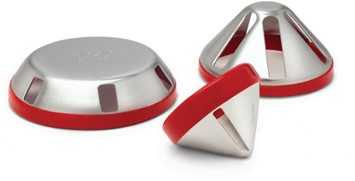
Plastic pipe deburring chamfering tools are lightweight and easily fit in your hand (chamfering means to cut off the edge, or bevel). These tools can quickly smooth out rough edges from the inside diameter (ID) and outside diameter (OD) of materials like ABS and PVC. A few spins of the tool can easily produce a 15° bevel for a smooth, chamfered pipe end so that solvent spreads evenly as pipe is joined.
Check Your Knowledge: Pipe Cutters, Reamers, and Deburring Tools
Complete the interactive knowledge test below
If you are using a printed copy, you can scan the QR code with your digital device to go directly to the interactive knowledge test.

Utility Knife
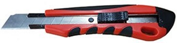
The utility knife is used for general-purpose or utility tasks. The utility knife was originally a fixed blade knife with a cutting edge suitable for general work such as cutting hides and cordage, scraping hides, butchering animals, cleaning fish, and other tasks. Today, the term “utility knife” also includes small folding or retractable-blade knives suited for use in the general workplace or in the construction industry.
Gasket Cutters
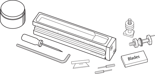
A tool incorporating a blade and designed to pivot around a center pin. It is used to make accurate circular cuts in a variety of materials that are used for gaskets in the piping industry. One design is the extension-style blade cutters shown in the figure below.
Measuring Tools
Measuring tools allow the pipe trades worker to verify accurate positions and dimensions. When using measuring tools, you may be required to use both metric and imperial measurement systems.
Imperial
Feet (ft or ‘) are divided into 12 equal parts called inches (in. or “). Inches may be further divided into equal parts called fractions. These fractions can be as large as [latex]\frac{1}{2}[/latex], but greater accuracy is achieved by dividing these parts of an inch into quarters, eighths, sixteenths or thirty-seconds.
The degree of accuracy you are likely to require in the pipe trade is generally no more than [latex]\frac{1}{32}[/latex] of an inch.
Metric
The base unit in metric measurement is the metre (m). A metre is divided into 100 centimetres (cm) or 1000 millimetres (mm). A millimetre is one-tenth of a centimetre. Millimetres are the most commonly used unit for precise metric measurement in construction and the pipe trades.
There is a wide range of measuring instruments used for checking clearances and tolerances. These include:
- Measuring tapes
- Steel rule
- Calipers
- Gauges
Pocket Measuring Tape
The pocket tape shown in Figure 34 is used to measure large layouts. It is the most widely used measuring instrument in the construction trades.
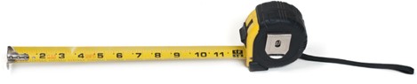
This tape is usually made from steel and is spring-loaded, allowing it to retract into its carrying case when released. The zero end of the tape is equipped with a hook that should slide along the tape a distance equal to the thickness of the hook. The sliding of the hook permits accurate internal and external measurements.
Pocket tapes range in length from 2 m to 7.5 m (6 ft to 25 ft.). Metric tapes are marked in one-millimetre graduations, while imperial tapes are graduated in thirty-seconds of an inch for the first 6 in. or 12 in., and in sixteenths of an inch for the remainder of the tape.
Pocket tapes often feature a retraction lock and belt clip and often have the case length indicated so that it can be used to measure inside dimensions (though not very accurately). Construction-grade pocket tapes are available in extra-wide widths to allow for greater standout length and to avoid buckling when taking long measurements unassisted.
Steel Tape
Although it is still commonly called the steel tape, it may be made of either flexible spring steel or plastic and is housed in a case with a crank-type handle for rewinding. Usually, it is 30 to 50 metres (100 to 165 ft.) long. It is ideal for large layouts in construction.
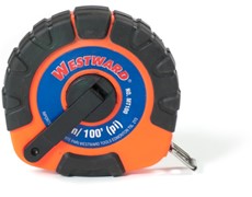
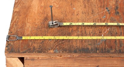
At the end of the steel tape is a combined ring and hook. When taking measurements, the hook is placed over the end of the object or, if possible, a nail is inserted through the ring to hold it in place. It is important when placing the nail that the very end of the ring marks the start of the measurement.
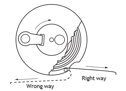
When you pull the tape out of its case, it is important to pull it out as shown in Figure 37. Rewind the tape in the same direction. Winding the wrong way stretches one side of the tape, causing the tape to curl when it is pulled from its case.
The winding handle of the steel tape is released by pushing a button on the opposite side of the case. If the tape seems to stick during rewinding, tap the case slightly on the side. If it continues to stick, pull out the tape fully and rewind it.
Circumference Tape/Pipe Diameter Tape
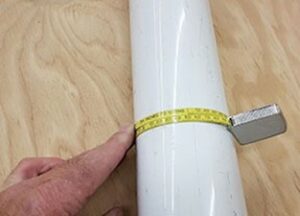
These tape measures typically have dual scales. Most models have a diameter scale on one side and a pocket tape measure scale on the other side used for measuring circumference at the same time. The user wraps the tape around a pipe and reads the number at the point where the tape overlaps.
Wrap-Around
The wrap-around is an inexpensive, yet indispensable pipe layout tool. It is often used by pipe trades workers who fabricate steel pipe. Wrap-arounds are about 12.5 cm (5 in.) wide and come in various lengths.
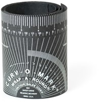
This tool is used for marking straight lines around pipe or as a straightedge. It is made of a flexible gasket-like material that has reasonable resistance to heat and cold. All wrap-a-rounds are available in two colours that designate material type and service temperature. Black material has a service temperature up to 175°C (350°F). Grey material is used for high-temperature applications up to 290°C (550°F).
Both material types are asbestos-free and are printed with a scale in inches or millimetres, a pitch chart, a tangent chart and other useful layout markings.
Carpenter or Framing Square
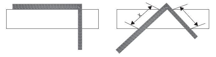
Another tool frequently used to measure and lay out larger dimensions on sheet and plate is the carpenter’s or framing square. It is also frequently used for layout and squaring large pipe. These squares can be marked in either imperial or metric measurements. The square has two blades set at 90° to each other. One blade (known as the body) is approximately 600 mm by 50 mm (24 in. × 2 in.), and the other, known as the tongue, is approximately 400 mm by 37.5 mm (16 in. × 1[latex]\frac{1}{2}[/latex]in.).
Various angles can be laid out with a framing square. For example, a 45° angle can be accurately laid out if you place the framing square so that the edge of a board intersects the sides of the framing square at equal measurements along each side.
Combination Squares
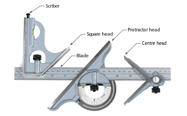
A combination square consists of a tempered steel blade onto which three interchangeable heads can be mounted. The three heads are the square head, the protractor head, and the centre head. The blade has scales engraved on it, and the heads slide on the blade in a central groove for easy adjustment. The heads can be adjusted to any position along the blade, or they can be removed easily so the blade can be used as a steel rule.
Pipe trades workers make regular use of the combination square (or combination set, as it is often called) because it can be used for many different purposes. Fitters use the combination set to:
- Square work
- Transfer measurements
- Lay out work
- Level surfaces
- Determine plumb
- Establish centres
- Lay out and check angles
- Measure recesses
Square Head (Set Square)
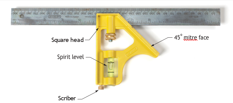
Square heads have a 90° square face and a 45° mitre face. Most square heads are equipped with a spirit level and a scriber. The square head can be used separately as a level. The figure below shows how the square head of a combination square is used to hold the blade at right angles to the edge of stock or flat bar.
Centre Head
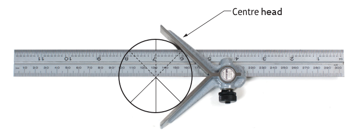
Centre heads have two equal arms that permit you to find the centre of large or small round stock. The centre head is used in combination with the steel blade to quickly locate the centre of the piece. To use the centre head, place it firmly against the round stock and scribe several lines in the stock along the blade, rotating the stock about 60° between each scribing. The point where the lines intersect marks the centre of the stock.
Protractor Head
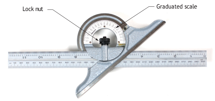
The protractor head is marked in degrees from 0 to 180°. With this head you can determine and check layout angles.
Thread Gauge
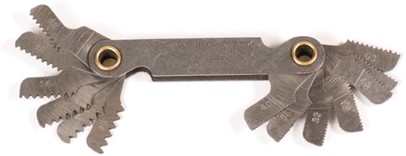
A thread gauge or screw pitch gauge is used to determine the pitch of various thread forms on bolts, screws, studs, or any threaded component.
Screw threads are spiral grooves of uniform shape and size formed on the inside of a hole or on the outside of a rod or pipe. Some types of thread taper to form a tight seal (pipe thread) while others don’t (bolt thread). These threads are measured as the number of threads per inch on imperial fasteners and as a direct measurement of pitch on metric fasteners.
The pitch of a screw thread is the distance from a point on one thread to the same or corresponding point on the next thread. Expressed in threads per inch, the pitch is equal to 1 divided by the number of threads per inch. For example, a screw with 10 threads per inch has a pitch of [latex]\frac{1}{10}[/latex]-inch (1 divided by 10).
In the metric system, the pitch is not expressed in inches or threads per inch, but as the distance between threads in millimetres, such as 1.0 mm, 1.25 mm, or 1.75 mm.
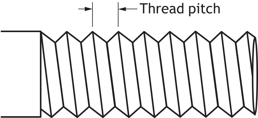
With a thread or screw pitch gauge, you can find pitch without using direct measurement or calculation.
These instruments are made up of a number of thin blades, each having V-shaped teeth cut along one edge that match a standard thread shape. Each blade also has a number indicating the number of teeth per inch or the pitch in millimetres.
To find the pitch of a screw thread, try to fit the appropriate gauge blade to the threads of the fastener being measured. Read the number on the gauge blade that matches your sample. The gauge blade must be held parallel with the fastener to get a correct reading.
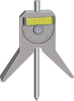
Centring heads (Figure 47) are used for fitting up welded pipe fittings and aiding in the setting of centre lines, establishing angles and marks for butt-ins, and locating points on pipes and tanks, One model, the Curv-O-MarkTM Standard Model, is used on pipe [latex]\frac{1}{2}[/latex]-in. diameter and larger. It has a 4-in. Y-type head and is fitted with an adjustable dial bubble protractor and a manually operated hardened centring pin.
Contour Marker
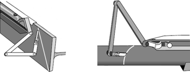
A contour marker tool is used for fitting up welded pipe fittings and may be used on almost any wye, tee, lateral or mitre joint directly on the pipe. This eliminates the time-consuming job of laying out a template. These instruments are very accurate but require some practice to use effectively when making fittings. These instruments consist of a frame that rests on the pipe or flange, a calibrated protractor, and a triple joint marking arm with a soapstone marking point (Figure 48).
Refractometer
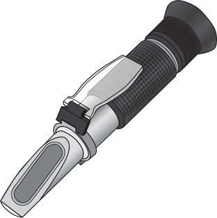
Refractometers are handheld, lightweight, portable instruments that utilize the measurement of refractive index to determine the concentration of ethylene glycol or propylene glycol antifreeze in sprinkler and heating/cooling systems. The two commonly used types of refractometers are analog and digital handheld units.
Hydrometer
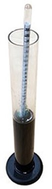
A hydrometer is an instrument used to measure the relative density of liquids based on the concept of buoyancy. They are typically calibrated and graduated with one or more scales, such as specific gravity.
The hydrometer makes use of Archimedes' principle, so the lower the density of the fluid, the deeper a hydrometer of a given weight sinks. Hydrometers are calibrated for different uses, including measuring the concentration of ethylene glycol or propylene glycol antifreeze in sprinkler and heating/cooling systems.
Levelling and Plumbing Tools
Levelling and plumbing tools include the hand level, torpedo level, line level, plumb bob, and chalk-line plumb bob. It is important that all levels be kept accurate. In a well-constructed project, every member is properly located, every horizontal pipe is level or properly graded, and every vertical pipe is plumb.
The Spirit Level
The spirit level (Figure 51) is a glass vial that indicates level or plumb. Some models use four glass vials for the spirit levels, while others use three (horizontal, vertical/level, and 45°).
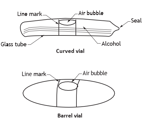
When four vials are used, the vials are slightly curved and filled with alcohol containing a small air bubble. When three vials are used, they are barrel-shaped, that is, wider in the middle. These vials are also filled with alcohol. Some levels may have an additional fourth vial used to check the pitch or grade of drainage pipe.


Hand Levels
Popular hand levels are about 600 mm (24 in.) long, but there are 1200 mm (48 in.) and 1800 mm (72 in.) types. Modern models are made from aluminum or plastic; older types were made of wood.
Hand levels should be checked regularly for accuracy. Hand levels that are not accurate should be adjusted or repaired.
To check the hand level for straightness, sight along the edge or place the level on a known flat surface, such as the top of a table saw, to see if it is in full contact with the surface. Then turn the level over and check again.
When using the hand level, take care not to drop it or bang it about, as this can move the bubbles out of position and make readings inaccurate. Make a habit of hanging the level up when you are not using it.
Torpedo Level
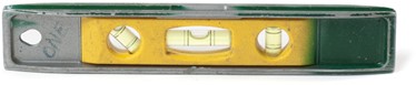
The torpedo level is a small aluminum level 200 to 300 mm (6 in. to 9 in.) long. It has a bubble for level, a bubble for plumb, and a bubble for 45°. Plumbers commonly use this tool, but in the carpentry trade it is also handy for checking spaces too small to accommodate a long level.
Line Level
The line level is a very short level with hooks at each end that allow it to be attached to a string line. The line should be as tight as possible, and the level placed near the centre of the line. One end of the line should be attached at the height desired, and the other raised or lowered until the bubble is centred. The line level is good for approximate measures only, such as for excavations, fence posts, or building lines.

Optical Levels
The optical level (also called a builders level or dumpy level) is a high-powered telescope equipped with crosshairs (similar to a telescopic sight for a rifle) centrally mounted on a bearing so that it can rotate only horizontally. A very sensitive spirit bubble is mounted on the telescope. When this bubble is centred, the instrument is level with the line of sight.
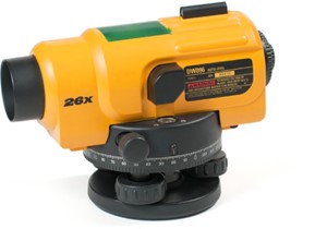
When mounted on a tripod, the optical level is adjusted with foot screws to centre the spirit bubble. As the optical level is rotated through a horizontal circle, the bubble may or may not have to be reset to centre, depending on the type of optical level being used.
Optical levels are used to establish horizontal reference points and to determine elevations and benchmarks.
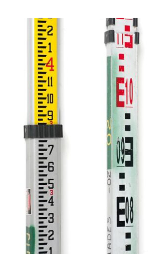
Optical levels used in the pipe trades are typically used with what is known as a level (or levelling rod).
There are many types of level rods. They can be made of wood, fibreglass, or aluminum alloy. They can be telescopic, or can come in sections that are bolted together or that fit one segment into the end of another. There are several different methods of displaying the scales. The type most suited to construction is the segmented type with a reflective face. These levels are easily dismantled for use in confined spaces, and a light source can be reflected on the scales for easy reading in poor light conditions.
Laser Levels
Laser is a word derived from Light Amplification by Simulated Emission of Radiation (LASER). A mixture of helium and neon gases is used to emit a very narrow beam of light that does not grow larger as it moves away from the source, which in this case is the laser level. The beam can be directed to any point, or it can be rotated continuously at various speeds. Laser beams used in these levels can be either red or green; red is most common but is harder to see than a green beam in bright environments. If used in very bright conditions, a sensor or detector may be required.
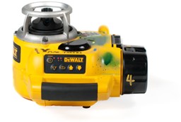

Do not look directly into a laser beam! Looking directly into the beam may be hazardous to your eyes. A quick flash of the beam is not a problem, but prolonged exposure should be avoided. The instrument must be positioned either above or below the worker’s line of sight.
The instruments can be supported in several ways. The most usual supports are tripods of various heights. They can also be clamped to columns or have small feet attached so that they can be set into or on pipes. Suspension frames are available to hold the instruments and aim them into pipes.
Sensors or Receivers
Only one person is required when using a laser levelling instrument. When the instrument is set up and the beam is rotating, it creates a level reference plane that can be detected with the sensor or receiver.
The sensors or receivers operate on batteries and have a narrow window through which the beam can be detected. When the beam is sensed, the detector shows a small coloured light or emits a sound. Sensors or detectors can be attached to the levelling rod or used by themselves to locate instrument height on walls, forms, or pipe work.
Plumb Bob
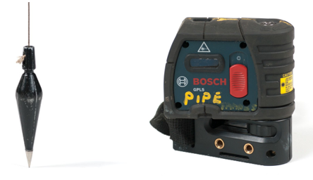
The plumb bob is used to establish a vertical line or a point directly above or below another point. Most plumb bobs are made of steel or brass and have a small threaded point that can be replaced if it becomes damaged. Some plumb bobs are hollow and filled with mercury, which adds weight and helps dampen movement without increasing size.
Plumb bobs vary in size from 250 g (9 oz) to 500 g (18 oz). On very large jobs, plumb bobs can weigh as much as 30 kg (65 lbs). These are held by piano wire and suspended in a large pot of oil to dampen movement.
Nothing should be allowed to touch a plumb bob line when it is suspended. The string should be attached through the centre hole of the bob and tied with the knot underneath.
The plumb bob is useful for plumbing piping, walls, posts, concrete forms, and other vertical objects.
Plumb bobs that use lasers are also widely available to save time when laying out pipe runs. Laser plumb bobs can be rested on the floor to transfer marks upward to the ceiling, for example.
Layout and Marking Tools
Marking tools are used by tradespeople to indicate exact points of reference for various procedures such as cutting or drilling.
Soapstone
Soapstone is a chalk-like substance used to mark heat-resistant layout lines on steel. The disadvantage of soapstone is that it can wipe off easily. Because of its brittle nature, soapstone is best used in holders, which may be round or flat.
Scriber (or Awl)
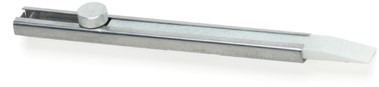
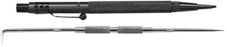
The scriber is a marking tool made with a hardened, tempered steel point that scratches mild steel and other relatively soft metals. The scriber or awl is used to make layout lines that are accurate and that have greater permanence than lines made with soapstone. Scribers are precision tools and should not be used for any other purpose (for example, as a toothpick).
Chalk Line
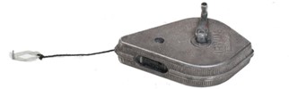
Chalk lines are used to lay out straight lines on a dry surface. A chalk line consists of a string on a retractable reel contained within a case. The case has a filler opening through which powdered chalk is poured. Every time the string is pulled from the case, it gets a coating of chalk, which is often red, yellow, or black.
The line is stretched tightly between two points on a surface, raised straight above the surface of the material at its centre, and then allowed to snap back. The snapping action deposits a straight line of chalk on the surface. The end of the line has a hooked eye that allows it to grip the edge of a surface such as plywood or hook over a nail driven into a structural member.
Divider and Trammel Points
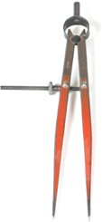
Another tool used in connection with layout and metal fabrication is the divider. You can use the divider to scribe circles and arcs or to locate one centre point in relation to another. As with the scriber, the hard, slender point must be ground frequently to keep it sharp, but the grinding should be done gently to avoid overheating and softening the metal.
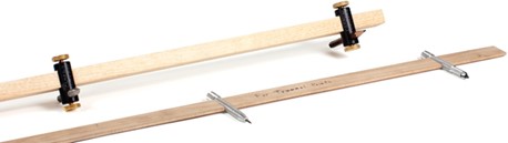
Trammel points are attached to a length of scaled material and are used for marking large circles or arcs.
Centre Punch
The centre punch has a tapered bit with a broad, sharp point. Punches are ground to an angle of 90°, which makes them durable tools, but they are also somewhat difficult to position accurately on a smooth work surface such as plate. They are used chiefly for punching small indentations in metal as a guide for starting a drill bit. For this procedure, you first mark the material to be drilled with a scriber or pencil, place the centre punch directly on the mark, and strike the head of the punch with a sharp blow from a hammer. The indentation will prevents the drill tip from slipping or “walking” out of position.

Prick Punch
The prick punch has a bit that is tapered to a very narrow, sharp point. The point of a prick punch is ground to an angle of 30°. This gives the prick punch a very thin point that makes it easy to place accurately on the workpiece. Often a prick punch is used to make the first indentation, then a centre punch is used to make a wider, deeper indentation. Although pipe trades workers do not make frequent use of a prick punch, it can be used in connection with drilling to make a small, accurate indentation at the intersection of two layout lines. Once this indentation is accurately located, the centre punch can be used to enlarge the indentation to a size that is suitable for the drill bit.
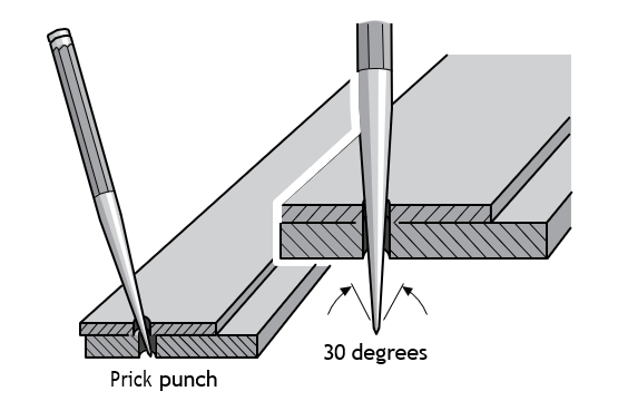
The prick punch is occasionally used to align holes in two or more sheets or plates. By inserting the tapered end of the prick punch through the holes drilled into the metal and moving it back and forth, you can accurately line up the holes.
Punches become dull in time, and like scribers, they need to be ground gently on a grinding wheel. As with scribers, you must take care not to overheat punches, as this will remove the temper from the metal.
Check Your Knowledge: Blades and Measurement Tools
Complete the Complete the interactive knowledge test below.
If you are using a printed copy, you can scan the QR code with your digital device to go directly to the interactive knowledge test.

Hammering and Prying Tools
Hammering tools are used in the pipe trades for striking and shaping materials, driving fasteners, and for hitting objects such as punches and pins. Prying tools assist the worker in removing unwanted fasteners or objects.
Claw Hammers
The head of a claw hammer is made of drop-forged steel, which is heat-treated to make it strong and long-lasting. Claw hammers come in different weights:
- Light claw hammers, which weigh about 370 grams (13 oz.), are used for finishing.
- Heavy claw hammers, up to about 900 grams (32 oz.) in weight, are used for framing.
The average framing claw hammer weighs between 570 and 680 grams (20–24 oz.).
Claw hammers also come in two claw styles: The straight (ripping) claw is used most often for ripping apart wooden members. The curved claw is better suited for pulling nails.
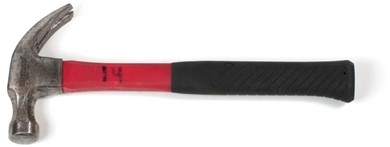
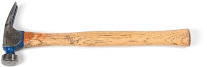
Figure 66 Claw hammers (BC Industry Training Authority, 2019). CC BY-NC-SA 4.0
Claw hammer handles are made of wood, fibreglass, or metal. The wood handle, usually fashioned from hickory, absorbs shock better than a metal handle.
The metal or steel handle is either hollow or solid and extends into the hammer head. The end of the handle has either a rubber or leather grip. The advantage of the metal handle is that it almost never breaks; but, as mentioned, it is not a good shock absorber.
The fibreglass handle offers a compromise between the wood and steel types. It stands up to wear better than wood and has superior shock-absorbing qualities.
The head of the claw hammer should be securely fastened to the handle. A head that is loose should be re-tightened with metal wedges.
The most important feature of a hammer is its balance. A hammer should feel comfortable in the hand, not head-heavy. The distribution of weight between the head and the handle, along with the length of the handle, determines the hammer’s balance.
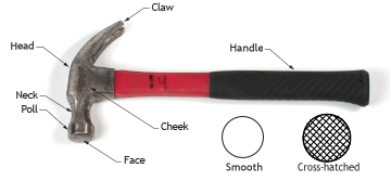
The hammer has two parts: the head and the handle. The head is made up of the following parts:
- face
- poll
- neck
- cheek
- claw
- adze eye
The face of the claw hammer is slightly curved and can be either smooth or cross-hatched. The cross-hatched hammer is usually used for framing because the hatch marks help prevent the hammer face from slipping off the nail. The cross-hatched hammer is not used for finishing because it can leave marks on the material.
Ball-Peen Hammers
The heads of steel-face hammers, such as ball-peen hammers, are made from high-grade alloy steel, drop-forged and heat-treated to the proper hardness. The ball-peen hammer (Figure 68) generally has a slightly rounded (convex) striking surface or face. The end opposite the face is shaped like a full half sphere and is called a peen.
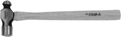
The size specification for a ball-peen hammer is determined by the weight of the head. Ball-peen hammers weigh from about 5.6 g to 1.35 kg (2 oz. to 3 lb.).
The ball-peen hammer can be used to set soft rivets or to strike chisels and punches. Small ball-peen hammers can be used to cut gaskets.
Sledgehammers
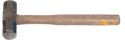
Sledgehammers are used for heavy work requiring significant force. They have longer handles than regular hammers and large rectangular heads. They weigh between 2.2 kg to 9 kg (5–20 lb.). Sledgehammers are also available for special applications, with soft heads or specially shaped heads. Handle length will vary with the weight of the head.
Soft-Face Hammers
Soft-face hammers have a surface that yields (or slightly compresses) when striking an object. Soft-face hammers are preferred when machined surfaces or precision parts are involved or when marring (damaging) a finished surface must be avoided. When working with parts that may be damaged by a metal hammer, the plastic-tip hammers or composition plastic hammers are good alternatives. You can also protect these parts by placing a piece of wood or brass over the surface before striking it with a hammer.
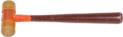
A plastic-tip hammer has a soft-face head and usually weighs between 225 g and 850 g (8 oz. to 2 lb.). Head diameters range from 18 mm to 32 mm ([latex]\frac{3}{4}[/latex] in. to 1[latex]\frac{1}{4}[/latex] in.). Replaceable plastic tips are usually available in different levels of hardness.
Another type of soft-face hammer has a specially compounded composition plastic tip rather than a clear plastic tip. Replaceable tips made of extra-tough nylon are also available. This hammer is usually furnished with a fibreglass handle with a rubber handgrip.
A brass-headed hammer also has a relatively soft face. It typically weighs between 450 g and 850 g (1–2 lb.). A brass-headed hammer can be used for driving gears or shafts, or for tapping shaft-mounted rocker arms.
A rubber mallet has a high-grade rubber head moulded onto the handle. The handle may have ridges and grooves to retain the head. Rubber mallet heads are all about the same size, but weights vary from between 450 g and 850 g (1–2 lb.).
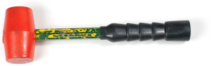
A rubber mallet should be selected when it is important not to scratch or dent a nearby surface. However, this hammer should not be used on sharp or hardened work. Rubber mallets are often used for steam-tracing tubing.
Lead hammers are used as “dead-blow” hammers because they don’t bounce back when striking. They also don’t mar or scratch delicate surfaces. Unfortunately, they tend to release and rub off bits of highly toxic lead dust and are no longer recommended. A safer alternative is a hammer with a hollow head filled with steel shot.
Chipping Hammers
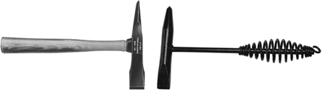
Chipping hammers are a regular part of the pipefitter’s or welder’s tool set. They are used after every weld deposit to chip slag from the weld bead. The heads of chipping hammers are made of forged alloy steel that has been hardened and tempered for maximum strength. The types available differ only slightly in design, and the most common design is the cone point on one end and a straight chisel edge on the other. They may have either a wire or a hardwood handle. The pointed tip of the slender cone and the thin, tapered chisel edge can reach slag in even the most confined area.
Wrecking Bar
The wrecking bar, also called a gooseneck, is from about 300 mm to 915 mm (12 in. to 36 in.) long, with the average length of about 600 mm (24 in.). It is made of heavy octagon-shaped steel with one end flattened and the other formed into a hook and claw for pulling nails. This bar is used for demolition, removing or stripping concrete formwork, and prying materials apart.

Pry Bar
The pry bar (also called the crowbar or long bar) is made in two styles: a pinch point and a wedge point. A pry bar is typically 1200–1725 mm (5–6 ft.) long and weighs about 15 kg (33 lb.). It measures about 40 mm (1[latex]\frac{1}{2}[/latex] in.) at the widest point. This bar is used for heavy work such as stripping concrete pipe sleeves and loosening compacted soil.
Wonder Bar
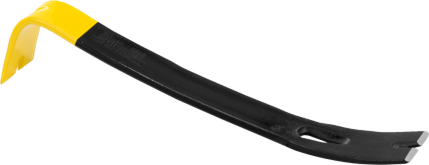
The wonder bar, which is about 400 mm (16 in.) long and made from flat metal. It is used for light-duty prying and stripping work. There is a claw on either end. One end is bent to 90°, while the other end has a slight bend for leverage when prying. It’s flat, wide surface area makes it a useful prying tool for general work.
Nail Claw
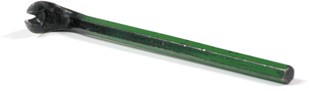
The nail claw, also called a cat’s paw, is a short bar, about 30 cm (12 in.) long. At one end, there is a claw for pulling nails, while the other end has a slightly bent chisel point for prying.
This tool is very useful for wood frame construction when nails have to be pulled from lumber. The small claw is driven under the nail head, and the tool is used to pull the nail free. Depending on the length, the nail is completely pulled or just started. A wrecking bar can be used to finish pulling larger nails.
Check Your Knowledge: Hammering and Prying Tools
Complete the Complete the interactive knowledge test below.
If you are using a printed copy, you can scan the QR code with your digital device to go directly to the interactive knowledge test.

Bracing and Clamping Tools
Bracing and clamping tools allow the pipe trades person to secure material while it is being fabricated or manipulated. It is important to know the various types of tools available to make your job safer and less difficult.
Vises
A good-quality vise is a very rugged piece of equipment. Vises hold material or a part at a bench or stand while work such as assembly, disassembly, welding or filing is being performed.
Bench Vise
The standard metal or bench vise is available in many sizes and variations. Many include a flat anvil surface on the back so that the tradesperson can use this area for forming metal.
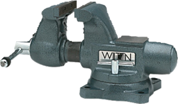
The size of a vise is usually measured by jaw width, but the maximum jaw opening should also be measured and considered when selecting a vise. Most good vises are available with a variety of jaw widths. Some vises have a set of curved, serrated jaws just above the winding screw, to hold pipe. The jaws on most styles may be replaceable.
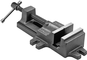
The Machine Vise
This type of vise is used to hold a workpiece for a machining operation. For example, a machine vise is used to hold a workpiece for drilling with a drill press. The vise can be bolted to the drill press table. Machine vise jaws are replaceable. The jaw face is usually smooth, to prevent the workpiece from becoming marred. The jaws may also have vertical and horizontal machined grooves to provide a gripping surface for round or irregularly shaped objects.
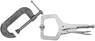
C-clamps are available in many different sizes (the width they will open to) and throat depths (the distance they can reach over a piece of stock). They come in sizes ranging from 25 mm to 120 cm (1 in. to 24 in.).
C-clamps are used to clamp a work piece to a drill press table when the item is oddly shaped or too large to fit into a vise. They are also often used to hold a workpiece during welding or soldering operations. When welding, you must be careful to protect the screws of the clamp from weld spatter.
It is also important that C-clamps not be over-tightened, as this can damage both the clamp and the work
Wood Vises
Wood vises are used to hold a piece of wood while it is being worked on. By using a vise, you can use both hands on the tool, increasing your speed, accuracy and control.
The wood vise has two flat metal jaws that are opened or closed by the action of a screw thread. Wood pads are usually attached to the inner faces of the jaws to prevent marring the work piece held in the vise.
Wood vises are bolted to the front of a workbench to add to their stability. The vise has a small sliding lever near the handle that releases the screw thread and allows for rapid opening or closing of the vise.
Pipe Vises
Pipe vises are holding devices used to hold pipe stationary while you perform operations such as cutting, reaming and threading. Some are attached to portable stands for use at the job site; others are designed to be mounted on a workbench only.
Bench-mounted Pipe Vises
The following pipe vises are permanently mounted to shop benches:
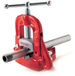
Bench Yoke Vise
The iron yoke and base, and the addition of steel jaws make this yoke vise a sturdy tool; like other bench-mounted vises, it features a pipe rest. The disadvantage of this type of vise is the uneven pressure it distributes by gripping only part of the pipe wall. Too much pressure will result in a damaged or deformed pipe. The typical maximum pipe capacity is 15 cm (6 in.).
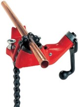
Top Screw Bench Chain Vise
The top screw chain vise is a popular bench-mounted type. Its main advantage lies with the holding chain, which distributes pressure evenly around the pipe. The crank handle is anchored to the base and can be swung freely and quickly in this top-mount position. The toothless jaws (chain) are sometimes specially coated with neoprene to avoid scoring the pipe. Pipe capacity is typically up to 20 cm (8 in.).
Bottom Screw Chain Vise
This vise is no longer popular and is usually found in established fabrication shops only. The construction is similar to that of the top screw model, except for the position of the screw, which makes it slower to operate and provides for application of less force. The pipe capacity is usually up to 4 in.
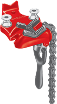
Open Side Vise
The open side vise is used for clamping a long length of pipe, but like the bench yoke vise, pressure is not distributed evenly around the pipe wall. It also maintains the disadvantage of only applying down forces from one side of the material. Pipe capacity is normally up to 10 cm (4 in.).
Portable Pipe Vises
The following pipe vices are portable for use on the job site:
Tri-stand Chain Vise
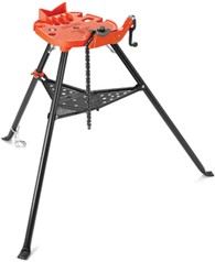
The tri-stand chain vise has a large base, hinged legs, and a folding tool tray, making it a complete, portable workbench. The chain type of vise is particularly popular because the chain holds a pipe quickly and securely, with uniform pressure. It is reasonably light and easily manoeuvrable to any area of a work site. To maintain stability it can be fastened with drop-in anchors or other appropriate fasteners to the floor, or it can be secured by the ceiling above with what is called the ceiling brace screw. This adjustable device allows the operator to quickly measure and cut a piece of 25 mm (1 in.) pipe to install plumb above the deck of the vise and tighten it against the ceiling for stability. Some models come equipped with a series of tubing benders formed into the deck of the unit. Pipe capacity is normally up to 125 mm (5 in.).
Tri-stand Yoke Vise
The tri-stand yoke vise is similar to the tri-stand chain vise in most ways, except that the holding device is a pair of jaws rather than a chain. This vise is limited to holding pipe sizes up to an including 6 cm (2[latex]\frac{1}{2}[/latex] in.). As is with the bench yoke vise, pressure is not distributed evenly around the pipe.
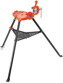
Top Screw Stand Chain Vise
Two pairs of legs connected by a pipe make this vice handy for working on long lengths of pipe that require support. The legs and connecting pipe along the centre are fabricated onsite by the pipe trades worker to suit the height and length required. A top screw stand chain vise, like most chain-style vises, will typically have a maximum pipe capacity of 13 cm (5 in.).
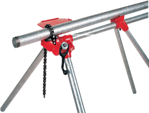
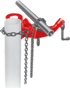
Top Screw Post Chain Vise
This is a light but strong vise that fits any shape or kind of post to create an instant work platform. This vise might be used on a job site where it is inconvenient to set up a tri-stand vise or when working on overhead piping. Pipe capacity is often 13 cm (5 in.) maximum.
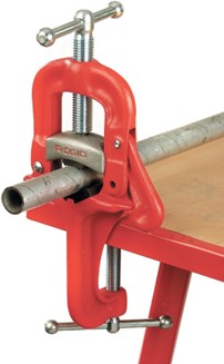
Portable Kit Yoke Vise
Similar to the post chain vise in application, the vice clamps to a plank, a workbench, or a flat beam or post up to 10 cm (4 in.) thick. Maximum pipe capacity of this vise is normally up to 6 cm (2[latex]\frac{1}{2}[/latex]in.).
Pipe Vises for Welding
Typically made of malleable iron, welding vises resist strain, heat, and distortion during welding tacking procedures (tack welding for fit-up of pipe). Screws and pins are used to hold the vise chains around the pipe.
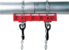
Straight Pipe Welding Vise
Used on mains and risers, the straight pipe welding vise holds and aligns pipe to be tacked. Pipe capacity typically ranges from 13 mm to 21 cm ([latex]\frac{1}{2}[/latex] in. to 8 in.).
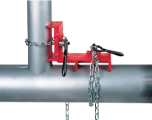
Angle Pipe Welding Vise
The angle pipe welding vise is used on headers and branches. It holds a branch line at a right angle to a main or header while layout and cutting work is done. This type of vise can allow the pipe trades worker to work unassisted to fit up the joint. Pipe capacity typically ranges from 13 mm to 30 cm ([latex]\frac{1}{2}[/latex] in. to 12 in.).
Elbow Pipe Welding Vise
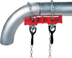
The elbow pipe welding vise is used on horizontal mains, risers and other right angle changes of direction. It permits lining up and holding of 90° elbows to the pipe until tacking is completed. Pipe capacity is often 6 cm to 21 cm (2[latex]\frac{1}{2}[/latex] in. to 8 in.).
Flange Pipe Welding Vise
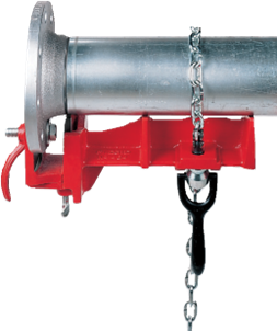
The flange pipe welding vise lines up the face of a flange at a right angle to the run of the pipe and holds it square for tacking. Pipe capacity is often 6 cm to 21 cm (2[latex]\frac{1}{2}[/latex] in. to 8 in.).
Check Your Knowledge: Bracing and Clamping Tools
Complete the Complete the interactive knowledge test below.
If you are using a printed copy, you can scan the QR code with your digital device to go directly to the interactive knowledge test.

Wrenches
A wrench is a tool that is used to grip and turn a fastener or fitting. You will need a variety of different wrenches that come in both standard and metric measurements. When selecting a wrench to use, you must first know the size of the nut or bolt head and then find a corresponding wrench. Usually, but not always, each end of the wrench is a different size and is stamped accordingly. Wrenches are available with straight or offset heads.
Different styles include:
- Open-end wrench
- Box-end wrench
- Combination wrench
- Tubing nut (flare nut) wrench
- Adjustable wrench
- Ratchet wrench
- Slug wrench
- Hexagon key wrench (Allen key)
- Socket wrench
- Ratchet torque wrench
- Pipe wrench
Open-End Wrench
An open-end wrench has an open head on each end. It was designed to fit both square-headed (four corners) and hex-headed (six corners) nuts and bolts. Even though it has the advantage of being easy to position, this style of wrench can wear down corners on the nut or bolt head because it only makes contact at two points.
While the open-end wrench may not provide as good a grip as a box-end wrench, it can be used in situations where you cannot reach all the faces of the nut or bolt head.

Box-End Wrench
The box-end wrench is an excellent tool for tightening and loosening nuts and bolts. Unlike the open-end wrench, the box-end wrench is made to grip the nut or bolt head on all sides. This prevents slipping and allows greater leverage.
The wrench must be slipped over the top of the nut or bolt head. The points around the inner circumference of the opening securely grip the bolt head or nut. These wrenches are available in either 6- or 12-point design. The 6-point wrench provides a more secure grip, but the wrench must be rotated further to achieve the next gripping location compared to the 12-point design.
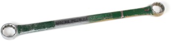
The two ends of the box-end wrench are usually different sizes. For example, a wrench with a [latex]\frac{5}{8}[/latex] in. opening on one end and an [latex]\frac{11}{16}[/latex] in. opening at the other end would be referred to as a [latex]\frac{5}{8}[/latex] × [latex]\frac{11}{16}[/latex] in. wrench. A metric wrench would have sizes such as 10 mm × 12 mm. The size of the wrench does not refer to the bolt diameter but rather to the distance across the flat of the nut or bolt head. Like the open-end wrench, the box-end wrench usually has the sizes stamped near the corresponding head.
Combination Wrench
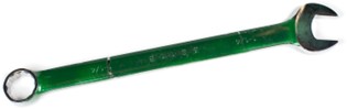
The combination wrench is an open-end wrench and a box-end wrench, with both ends of the same size, combined into one tool. All the features of open-end and box-end wrenches apply also to a combination wrench. The combination wrench is available with 6- or 12-point box-end heads and in a wide selection of sizes and lengths.
Tubing Nut Wrench (Flare Nut Wrench)
The tubing nut or flare nut wrench is specially designed to provide a secure grip on line fittings. These wrenches have a slot through which the line or tube can be passed to allow a grip that is almost equal to a box-end wrench. This grip prevents wearing of the fitting hex nut corners during removal or installation, as might occur with an open-end wrench.
These wrenches are available in both imperial and metric, in a variety of sizes, and in both 6- and 12-point design.

Adjustable Wrench
The adjustable wrench, often referred to as crescent wrenches has the provision for adjusting the opening to suit the nut or bolt being turned. The adjustable jaw is moved by a knurled nut. The size of all adjustable wrenches is designated by the wrench length, which varies from 10 cm to 61 cm (4 in. to 24 in.). For example, the 4 in. wrench has [latex]\frac{1}{2}[/latex]in. jaw capacity, while the 12 in. wrench has a [latex]\frac{15}{16}[/latex] in. capacity.
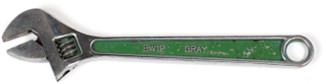
Adjustable wrenches are useful but should never be used as a substitute for an open-end or box-end wrench. Adjustable wrenches can be pulled in either direction for light loads but develop their greatest strength when pressure is applied to the side of the wrench with the fixed jaw. Always be sure that the wrench is adjusted as tightly as possible against the nut or bolt head before attempting to turn it. This will act to avoid rounding the corners of fasteners when installing or removing them.
Ratchet Wrench
A ratchet wrench is a tool that is useful in tight places where it is impossible to reposition the wrench after each turn. Instead, you just move the handle back and forth once the box end is positioned over the fastener. It is not recommended for heavy applications.

Slug Wrench (Striking Wrench)
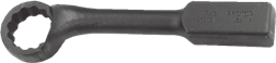
A slug wrench (or striking wrench) is a specialized thick, short, stocky wrench with a block at the end of the handle specifically designed for being struck with a hammer in order to add greater force. Used commonly with large fasteners, slug wrenches also provide shock and high force used to release large or stuck nuts and bolts, and are useful when space does not allow room for a large wrench.
Hex Key Wrench (Allen Key)
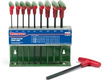
The hex key or Allen key wrench is typically an L-shaped bar of hexagon-shaped tooled steel. It is made to fit the hexagon shaped hole found in some fasteners. Hex keys are classified by the size of their hexagonal stock measured across the hex flats. They come in either imperial or metric measurements, with the size usually stamped on the wrench. They are also available as a socket wrench, in a folding set, or as a series of T-handled drivers.

Socket Wrenches
Socket wrenches are designed to be used for turning fasteners that cannot be easily accessed with a standard wrench. Socket wrenches may have 4, 6, 8, or 12 points. The 6- and 12-point sockets are most common. The 6-point socket is stronger and will do less damage to the fastener than a 12-point socket
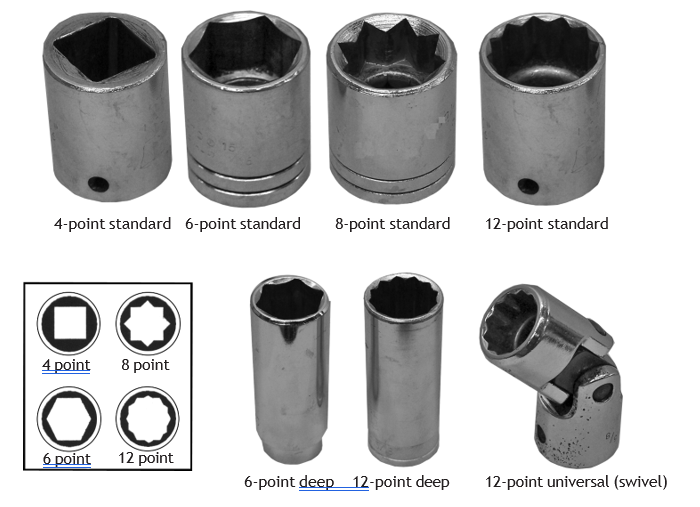
A basic socket wrench set is made up of a handle and several barrel-shaped sockets. Each socket has a square hole on one end that fits directly into the drive lug on the socket wrench handle.
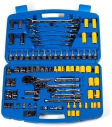
The other end of the socket looks like a box-end wrench and has 6, 8, or 12 points. With the socket firmly attached to the wrench handle, the socket is placed over the nut or bolt head and the handle is moved to loosen or tighten the fastener.
The universal flex or swivel socket permits the socket to be used at various angles by the swivelling action of the socket head. The deep socket allows you to loosen a nut on a stud or bolt that has a large number of threads showing when standard sockets would not be long enough to reach the nut.
Socket sizes are marked on the outside of the socket and indicate the head size of the fastener that they will fit. Other special sockets include those designed for removing and replacing oil pressure and temperature sending units, spark plugs, and sockets designed for use with impact wrenches.
Impact sockets have stronger construction and are not chrome plated, since the chrome would crack and flake off. The thick walls and heavy construction allow them to take the shock of the impact. For this reason, standard sockets should never be used with impact wrenches.
The square drive is the end of the socket that attaches to the socket handle. The square drives range in size from 6 mm ([latex]\frac{1}{4}[/latex] in.) to 5 cm (2 in.). The 6 mm ([latex]\frac{1}{4}[/latex] in.) through 19 mm ([latex]\frac{3}{4}[/latex] in.) sizes are most common. The drive size is measured in inches on both metric and imperial sockets.
Some socket handles have a small, half-exposed ball bearing centred on one side of the square drive. When the socket is fully pushed onto the socket handle, a machined groove or mating hole aligns with the recessed ball bearing to assist in retaining the socket.
Ratchet Torque Wrenches
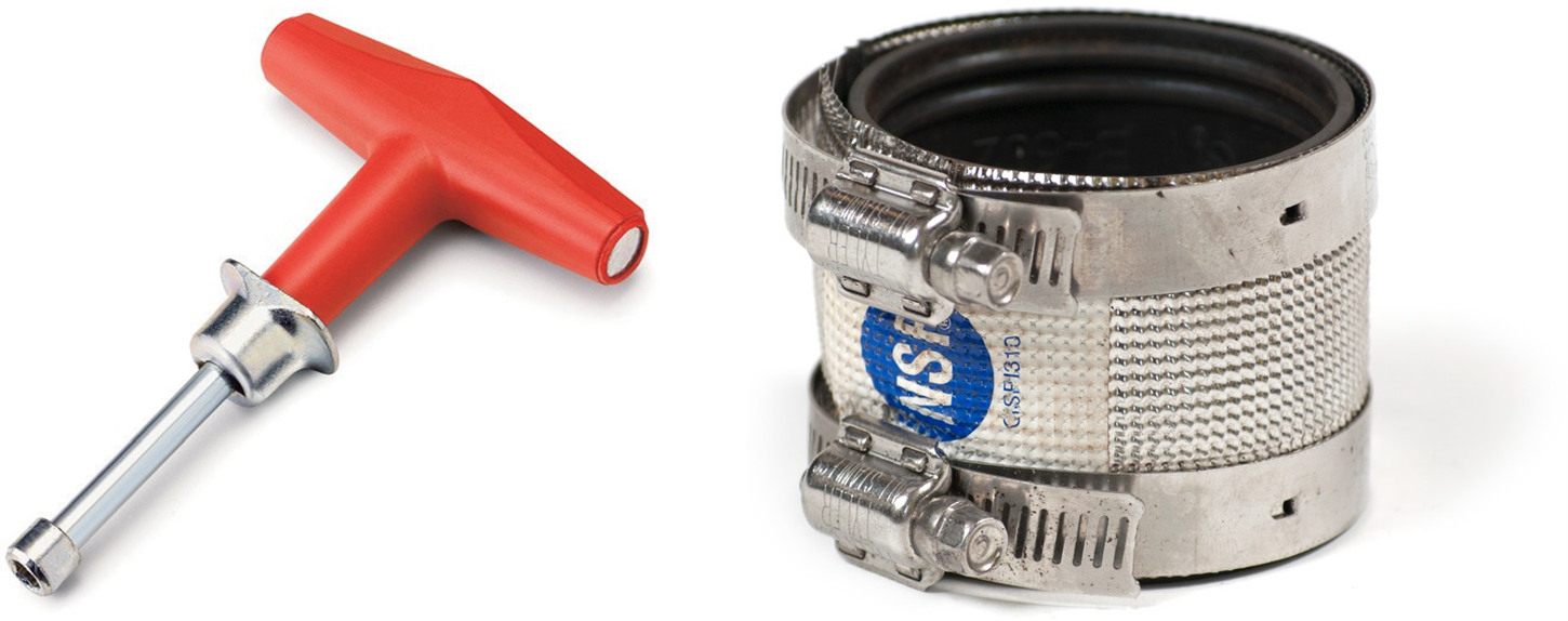
Specifically useful for installing no-hub cast iron soil pipe couplings, ratchet torque wrenches tighten with a quick ratchet action and automatically release when they reach a pre-set amount of torque (twisting force). The [latex]\frac{5}{16}[/latex] in. driver model is common and is pre-set to 60 inch-pounds. The [latex]\frac{3}{8}[/latex] in. model is pre-set to 80 inch-pounds.
The click-type torque release function prevents over-tightening or damaging of gear clamps when installing no-hub couplings.
Pipe Wrenches
A pipe wrench is used for turning pipe and other round objects. The sharp jaw teeth of the pipe wrench will dig in and mar (damage) the surface. A pipe wrench should not be used to turn bolts or nuts unless the head of the bolt has been damaged and will not accept a straight-faced wrench or socket.
Before using a pipe wrench, remove any grease or dirt from both the part to be turned and the pipe wrench jaws. A small wire brush or scribing tool is adequate. Adjust the movable jaw so that the work is gripped near the centre of the jaws. Pull carefully until the wrench has a good bite on the work. Then exert the force necessary to turn or tighten the work. Pipe wrenches should never be used on hardened surfaces since the jaw teeth may be dulled or chipped.
A variety of wrenches are used for gripping and turning pipe and fittings. The type of wrench selected for a job depends on pipe size, pipe material, and the amount of working space available.
The following wrenches are most common to the piping trade:
- Straight pattern pipe wrench
- End pattern pipe wrench
- Raprench
- Offset pattern pipe wrench
- Stillson pattern pipe wrenchs
- Vertical pipe wrench
- Rapidgrip wrench
- Spud wrench
- Hexagonal pipe wrench
- Compound leverage pipe wrench
- Chain wrench
- Chain tong
- Strap wrench
- Basin wrench
- Plastic nut basin wrench
- Internal wrench
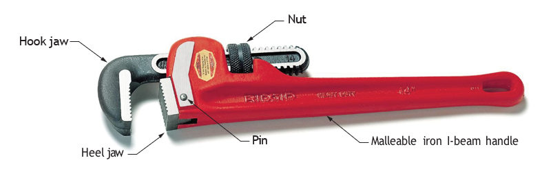
The jaws of pipe wrenches have teeth for gripping round objects. The heel jaw is attached to the handle, while the hook jaw can be made to move in and out by adjusting the nut on the threaded section of the hook jaw. Both the shank of the hook jaw and the nut are held in position by the wrench housing.
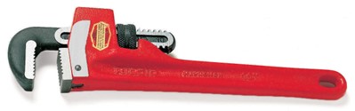
Straight Pattern Pipe Wrench
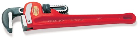
Available in at least ten models, each is designed for a certain range of pipe sizes. The smallest is typically 150 mm (6 in.) long and has a pipe capacity of [latex]\frac{3}{4}[/latex] in.; the largest is 1500 mm (60 in.) long for use on 8 in. pipe. Pipe wrench sizes are designated by their length, measured from the tip of the handle to the inside of the hook jaw, when fully extended. Like the other standard wrenches shown here, this wrench comes with either an aluminum or cast iron handle.
End Pattern Pipe Wrench
These wrenches have a 45° opening and can be used when working in tight quarters or next to a wall or a corner. Produced in about eight different sizes, the end pattern pipe wrench accepts pipe sizes ranging from 19 mm to 13 cm ([latex]\frac{3}{4}[/latex] in. to 5 in.).

Raprench (Rap-Wrench)
The Raprench has a pipe diameter scale on the hook jaw for size setting. It is available in several models with different pipe size capacities.
This wrench has a deeper, broader hook jaw housing with a smooth, flat, hardened surface that is used like a hammer to jar loose pipes and fittings that have seized. The Raprench can usually accept pipe sizes up to 38 mm (1[latex]\frac{1}{2}[/latex] in.).
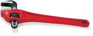
Offset Pattern Pipe Wrench
This unique pattern has the jaw open parallel to the direction of the handle. It also has a narrower hook jaw head. These features allow easy entry to tight spots. Several models are marketed, with pipe capacities of 5 cm, 6 cm, and 8 cm (2 in., 2[latex]\frac{1}{2}[/latex]in., and 3 in.).
Stillson Pattern Pipe Wrench
The forefather of the modern pipe wrench, the Stillson pattern pipe wrench, has a pipe diameter scale on the hook jaw, for size setting. It is available in several models with different pipe size capacities, with the maximum pipe size 6 cm (2[latex]\frac{1}{2}[/latex] in.).
Vertical Pipe Wrench
This wrench is manufactured without a long handle and requires the user to insert a handle into the head assembly. It can be used on either vertical or horizontal pipe in closely confined areas and operates in a way similar to that of a basin wrench. It is especially useful for underground valve locations. Pipe capacity is typically 5 cm (2 in.) maximum.
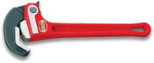
RapidGrip Wrench
The rapidgrip wrench has a spring-loaded jaw designed for quick ratcheting action. It allows for one-handed operation while the worker uses the other hand to hold a backup wrench. It has a distinctive jaw designed to accept multiple sizes and shapes of material. Maximum jaw capacity is usually 5 cm (2 in.).
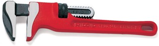
Spud Wrench
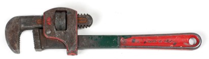
This tool (also known as a monkey wrench) utilizes smooth, flat, narrow jaws that are ideal for use on square or rectangular stock, such as a flat-edged fitting.
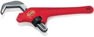
Hexagonal Pipe Wrenches
The hexagonal wrench appears in two designs: straight and offset. Both types give a multi-sided grip, but the main difference between the two is the extra-wide opening of the offset, which is ideal for securing drain nuts on tubs and sinks. Thin, smooth jaws fit into tight spaces easily.
Compound Leverage Pipe Wrench
This wrench has the ability to multiply leverage numerous times. The chain wrench part attaches to the pipe adjacent to the fitting and imparts a holding force opposite in direction to the turning force of the hook jaw, which grasps the fitting. It is ideal for loosening seized joints.
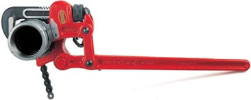
This wrench works on right- or left-hand threads and comes in several models, with pipe size capacities of 5 cm to 20 cm (2 in. to 8 in.).
Chain Wrenches
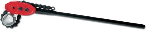
Chain wrenches and chain tongs provide another method of tightening threaded pipe and fittings. They have the advantage of distributing pressure evenly without crushing and work well in tight working areas, since the only clearance needed is sufficient space to wrap the chain around the pipe or fitting.
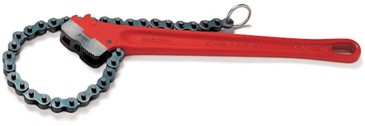
Chain Tongs
Tongs are manufactured in various sizes that can be used for pipe diameters from 6 mm to 30 cm ([latex]\frac{1}{4}[/latex] in. to 12 in.). When the teeth on one end of the double-ended Tongs jaw have become dull, the head can be unbolted and reversed. Single-ended Tongs (not shown) have a head that is non-reversible.
Strap Wrenches
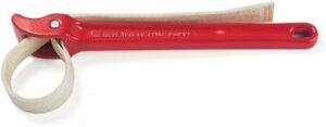
Designed for polished or chrome pipe, the strap wrench has a woven nylon strap to give a tight grip. The various models have different strap lengths and widths, as well as different handle lengths. The two basic sizes have pipe capacities of 5 cm and 13 cm (2 in. and 5 in.), and handle lengths of 300 mm (11[latex]\frac{3}{4}[/latex] in.) and 450 mm (18 in.). A powdered Rosin product can be applied to the strap for increased friction.
Basin Wrenches
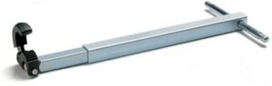
The spring-loaded jaws of a basin wrench allow one-hand ratcheting on nuts in hard-to-reach areas. A tension plug holds the tool’s head at any angle up to 90°. This wrench is particularly handy behind sinks and lavatories, where it is impossible to use a standard wrench.
The telescoping basin wrench can be adjusted for length. Its maximum capacity is 6 cm (2[latex]\frac{1}{2}[/latex] in.). The non-telescoping model has a maximum capacity of 32 mm (1[latex]\frac{1}{4}[/latex] in.).
Plastic Nut Basin Wrenches
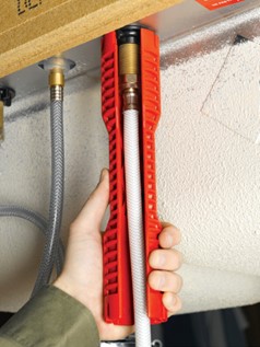
Plastic nut basin wrenches are a type of basin wrench that is designed for turning plastic mounting nuts on faucets, sprayers and ballcocks. They often have a hole through the barrel to allow a screwdriver shaft to fit through and help increase torque.

Internal Wrench
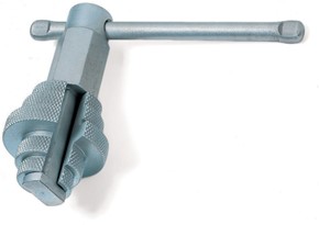
The internal wrench is used to hold pipes, nipples, and fixture connections in place from the inside while a nut is tightened down. The knurled head of some types is reversible to accept sizes from 2.5 cm to 5 cm (1 in. to 2 in.).
Pliers
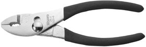
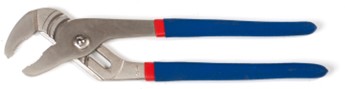
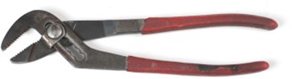
Pliers are used to increase gripping power when holding relatively small-diameter objects. Of the many types and designs that are produced, the three pliers illustrated below are the types most commonly used in the piping trades.

Never use pliers for turning nuts or bolts, as the sharp teeth will round off the corners and badly damage the nut or bolt.
Combination Slip-joint Pliers
Combination slip-joint pliers are the most common general-purpose pliers. They can be adjusted to two sizes by means of a sliding pivot that allows the jaws of the pliers to open widely for gripping larger items. The jaws have sharp, hardened cross teeth to grip the object on which you are working.
Arc-joint Pliers
Arc-joint pliers are made in various sizes with maximum capacities up to 10 cm (4 in.). The tongue and groove design provides maximum power at all openings. This type of joint design’s advantage is that it is less prone to slipping under force due to increased surface area. Most piping trades people will refer to these simply as Channellock pliers (that manufacturer being the innovator of this product).
Water Pump Pliers
Water pump pliers have a maximum pipe capacity of 5 cm (2 in.). They are a style of slip-joint plier having multiple positions. The multiple slip-joint setup provides for rapid changes of jaw opening.
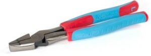
Linesman Pliers
Linesman pliers are non-adjustable, in that they have a fixed pivot point, and are easy to use for a multitude of tasks from bending metal to tying wire. Originally designed for the electrical field, their flat serrated jaws are equipped with cutters for snipping wires.
Needle-Nose Pliers
Needle-nose pliers come in a variety of sizes and styles, some incorporating a cutting surface. Many needle-nose pliers are useful in bending wire into curves or circles, and for retrieving small parts from equipment and hard to reach places.
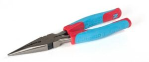
Diagonal or Side-Cutting Pliers
Diagonal or side-cutting pliers are made with a diagonally cut head or face and a hard steel cutting edge to cut wire or other metal objects close to the surface. Diagonal cutters are especially useful for removing cotter pins (pins used for securing parts to equipment) and for trimming cotter pins to the desired length after installation.
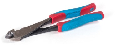
Locking Pliers
Locking pliers are produced by several manufactures in a multitude of styles but are often referred to as Vise-Grips due to the popularity of that brand. They have a built-in spring-type mechanism which can be locked into position and released by pulling or squeezing a release lever. Locking pliers come in several sizes and styles and are available either with straight, cutting or curved jaws.
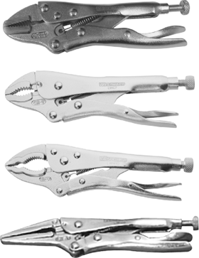
Wire Strippers/Crimpers
Wire strippers/crimpers are useful when making multiple wiring connections or splices. They include squared and rounded crimping heads, multi-gauge wire strippers, and a set of wire cutters. Most types also have small holes that enable smooth, quick cutting of small diameter machine bolts.
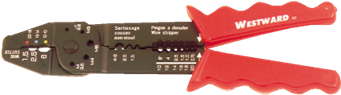
Screwdrivers
Screwdrivers are available in a variety of lengths and sizes. The length of a screwdriver is measured from the tip to where the handle joins the blade. Lengths range from 38 mm to 60 cm (1[latex]\frac{1}{2}[/latex] in. to 12 in.) or more, with the shorter lengths known as “stubbies.” Stubbie screwdrivers are used only when space will not permit use of longer screwdrivers.
Some common screwdriver types include:
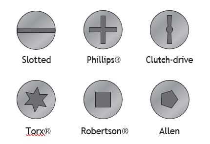
- Slotted
- Robertson
- Phillips
- Ratchet
- Stubby
- Offset
- Torx
- Clutch drive
- Allen
The parts of a screwdriver are the head, handle, ferrule, shank, blade, and tip. The length of the blade, as mentioned above, indicates the size of a screwdriver. Some screwdrivers may have square shanks that permit turning with a wrench, when required for extra torque.
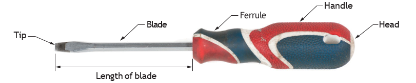
Slotted Screwdriver
Although almost completely replaced by the Robertson head in modern construction, the slotted screwdriver was at one time the most commonly used screwdriver, and is still sometimes referred to as the “conventional“ screwdriver. It comes in many lengths and tip sizes. When you select a screwdriver for slot screws, make sure that the tip is as wide as the diameter of the screw head and that it is as thick as the slot size. The figure below shows the correct fit for slot screwdrivers.
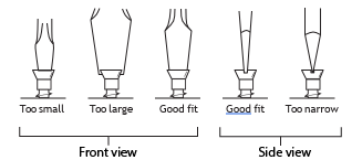
If the tip of the screwdriver becomes worn and rounded, reshape it by filing or grinding, often called dressing. Figure 129 shows correctly and incorrectly ground screwdriver tips.
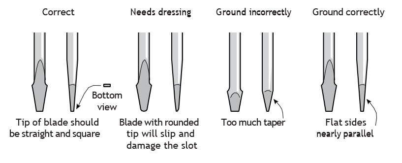
Robertson Screwdriver
The advantage of the Robertson-head system is that it has a square-shaped socket in the screw head and a square protrusion on the tool. Both the tool and the socket have a taper, which makes inserting the driver easier and also tends to help keep the screw on the tool tip without the worker needing to hold it there.
Robertson screwdrivers are named after Canadian inventor P.L. Robertson, who invented the system in Milton, Ontario, in 1908.
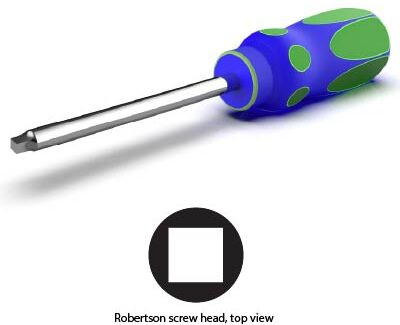
Robertson-head screwdrivers are available in range of tip sizes. Robertson screwdrivers have a unique system of colour coding that are indicated on their handle according to the following colour and sizing system:
|
Colour |
Tip Size |
Screw Sizes |
|
Orange |
No. 00 |
#1 & #2 |
|
Yellow |
No. 0 |
#3 & #4 |
|
Green |
No. 1 |
#5, #6, #7 |
|
Red |
No. 2 |
#8, #9, #10 |
|
Black |
No. 3 |
#12 and larger |
Phillips Screwdrivers
Phillips screws and drivers were known as “crossheads” when Henry Phillips first developed them in the early 1930s. The importance of the Phillips screw design lies in its self-centring property, useful on automated production lines that use powered screwdrivers. The Phillips screwdriver is available in the following sizes: No. 00, No. 0, No. 1, No. 2, No. 3, and No. 4, with No. 00 being the smallest and No. 4 the largest.
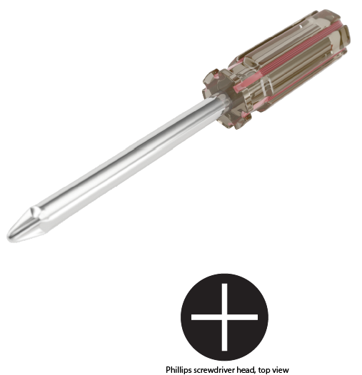
Ratchet Screwdrivers
The ratchet screwdriver typically has different tips for fitting into slotted, Robertson, and Phillips screws. To speed up a job, the ratchet on the ferrule of the driver can be set to install or remove a screw without the operator having to release the handle to regrip the driver. It can also be set to a locked position to permit the driver to be operated as an ordinary screwdriver.
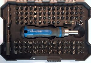
Stubby and Offset Screwdrivers
The stubby screwdriver is available in all sizes of slot, Robertson®, and Phillips® tips. The blade and handle are very short.
Another design is the offset screwdriver, which enables the operator to reach into tight spaces. Most offset designs are Z-shaped, with the face of the tip at one end at right angles to the face of the tip at the other end.
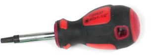
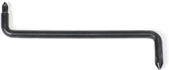
Torx Screwdrivers
Torx is the trademark for a type of screw head characterized by a 6-point star-shaped pattern. By design, Torx head screwdrivers and screws resist cam-out (slipping out of the screw head) better than Phillips head or slot head screws. Where Phillips heads were designed to cause the driver to cam out, to prevent over-tightening, Torx heads were designed to prevent cam-out.
Torx screws are commonly found on automobiles, motorcycles, hard disk drives, and consumer electronics. Initially, they were sometimes used in applications requiring tamper-resistance, since the drive systems and screwdrivers were not initially widely available.
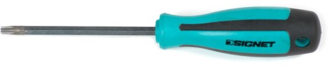
Never use an Allen key wrench on a Torx screw. The head of the Torx screw may appear to fit an Allen key wrench, but you will find that as soon as force is applied, the corners of both the wrench and screw may be damaged.
Clutch Drive Screwdriver
The clutch drive screwdriver is used in the automotive and manufacturing industries. The driver tip must exactly match the size of the head. The head of the screw is held firmly by the driver tip; if a slot or Phillips driver were used with it, the screw might slip out.
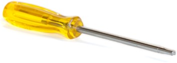
Allen Head (Hex Head) Screwdrivers
Similar to the Allen key wrench, Allen head screwdrivers have a hexagonal head used to drive screws that have a matching hexagonal socket in the head.
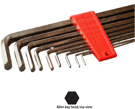
Check Your Knowledge: Pliers and Screwdrivers
Complete the Complete the interactive knowledge test below.
If you are using a printed copy, you can scan the QR code with your digital device to go directly to the interactive knowledge test.

Tubing Benders
An annealed (softened by heating) copper tube can easily be bent across your knee, but its original circular cross section will be flattened in the process because the lateral forces across the part being bent haven’t been contained. The use of tubing benders enables smooth corners to be formed in tubing while retaining the original profile. Tube benders range in styles from simple spring benders to complex mechanical benders that are used for larger bending operations.
Maximum capacities for tubing benders will be dictated by tubing diameter, wall thickness, style of benders and type and temper of the material.
Spring Tubing Benders
These types of benders form quick changes of direction in small-diameter soft-drawn copper and aluminum tubing. Capacities range from 6 mm to 22 mm ([latex]\frac{1}{4}[/latex] in. to [latex]\frac{7}{8}[/latex] in.) OD.
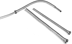
Compression Hand Lever Benders
This bender is designed for bending stainless steel, steel, copper, and aluminum tubes of several sizes.
It is equipped with a degree dial on the bending wheel allowing the user to easily read any angle of the bend.
Tube size dimensions for this type of bender usually range from 5 mm to 19 mm ([latex]\frac{3}{16}[/latex] in. to [latex]\frac{3}{4}[/latex] in.) OD.
Parts of the Compression Hand Lever Bender:
- Bending Wheel: provides the circular form that the tube rotates around during the actual bending process.
- Placement Link: has indicators that are used to correspond with measurements that are marked on the tubing.
- Pull Handle: assists to draw the tubing around the bending wheel to the desired bend required.
- Tubing Fastener: acts to lock the tubing in place during the bending process.
- Stationary Handle: supports the bending wheel while the bender is being use.
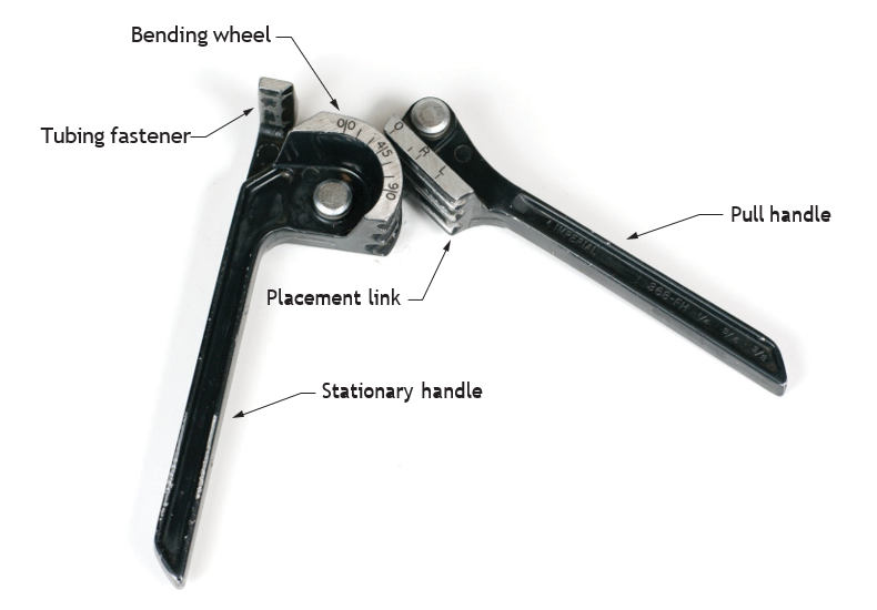
Figure 138 Parts of the compression hand lever bender (BC Industry Training Authority, 2019). CC BY-NC-SA 4.0
Swaging Tool
A swaging tool is sometimes used to join two lengths of tubing together. The tool is driven into the end of an annealed (softened by heat treating) tube. This forms a socket that will accept the end of the other piece of tube perfectly.
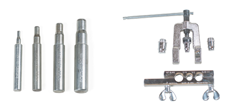
Some swaging tools come in sets with a dedicated tool for each tube size, while others may have stepped formations to be used for multiple sizes.
Flaring Tool
Flaring tools are used to provide a mechanical joint in tubing systems. When flaring, the end of the tube is clamped into a flaring block to the correct height. The body of the tool is placed over the flaring block and a screw is turned to drive a steel cone toward the end of the tube. The better versions of flaring tools have the steel cone moving eccentrically, which sweeps the edge of the tube as it lowers forming a 45° flare.
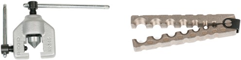
During tube installation, the flare is seated to a fitting with the inside of the flare against the cone-shaped end of the fitting, and the flare nut is screwed onto the fitting, pulling the inside of the flare against the seating surface of the fitting.
PEX Connecting Tools
Cross-linked Polyethylene (PEX) has become very popular for use in residential water plumbing because of its flexibility. PEX tubing has also become the most popular material to transport water in hydronic radiant heating systems. Methods of joining the tubing include crimping, compressing, expanding and stainless steel clamping. It is unable to be welded with solvents.
Crimping Tools
The standard method for connecting PEX pipe to brass or plastic PEX insert fittings uses a copper crimp ring and a crimping tool. The copper crimp ring is placed over the pipe, the fitting is inserted inside the pipe, and the copper ring is crimped over the pipe and fitting using the crimping tool. The compression forces of the tool deform the ring to hold tightly against the tube and fitting, providing a reliable seal.
These tools are available in single size models, multiple size models, and a special style used for crimping in tight locations.
The Stainless Steel Clamp (SSC) method uses special clamps designed for PEX connections. The fittings used here are the same used in the standard connection method above, but in this method the SSC fastens the PEX tube to the fitting. A special SSC crimping tool is used to tighten the clamp around the tube and fitting.
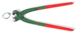
Crimp Ring Removal Tool (Decrimper)
PEX crimp fittings can be reused after removal with the use of this crimp ring removal tool. Its jaws are set to a depth that will bite through the crimp ring and tubing, but won’t damage the fitting. Some types will work on multiple sizes of tube, while others are size-specific.
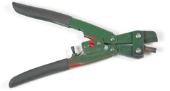
PEX Expander Tools
The expansion method involves using an expander tool to increase the diameter of the PEX tube and a PEX collar, or ring. Special expansion fittings are inserted into the tube once expanded, which shrinks back to shape around the fitting. This method is unique and specific to one manufacturer’s product
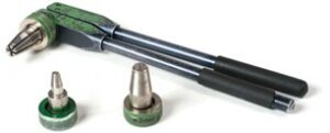
The shape memory capability of certain types of PEX tubing allows for this distinctive joining capability. Not all types of PEX tubing can be joined through the expansion process. The shape memory capability of PEX-A tubing (which is tubing that is manufactured using the Engel method) allows for this distinctive joining capability. PEX tubing types B and C, which are manufactured differently, must use crimp rings or SSCs.
Hand Threading Tools
The threaded piping used in some plumbing installations for the delivery of gases or fluids under pressure has a threaded section that narrows to create a seal (in contrast to the straight thread pattern commonly found on bolts). This is called tapered thread.
Pipe Thread
The seal provided by a threaded pipe joint depends upon the diminishing seal created by the threads and sometimes on the presence of a sealing coating, such as thread seal tape (Teflon tape), or a liquid or paste applicant such as pipe dope. Pipe dopes and tape are applied to male (external) threads to lubricate the mating of the threads, thereby reducing friction and allowing the joint to be properly tightened to specifications without binding.
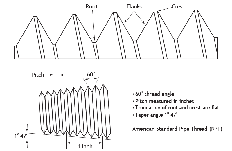
The standard developed in North America for tapered threads is ANSI/ASME standard B1.20.1 and is known as National Pipe Thread (NPT) or sometimes still referred to as American Standard Pipe Thread (ASPT).
The rate of taper for all NPT threads is [latex]\frac{1}{32}[/latex] in. per inch (1° 47′) and the grooves that create the threads are formed at 60° angles.
Commonly used sizes are [latex]\frac{1}{8}[/latex], [latex]\frac{1}{4}[/latex], [latex]\frac{3}{8}[/latex], [latex]\frac{1}{2}[/latex], [latex]\frac{3}{4}[/latex], 1, 1[latex]\frac{1}{4}[/latex], 1[latex]\frac{1}{2}[/latex], and 2 inch, appearing on pipes and fittings by most North American suppliers. Sizes smaller than [latex]\frac{1}{8}[/latex] in. are occasionally used for compressed air, while sizes larger than 2 in. are uncommon, due to the use of alternative methods of joining that are more common with these larger sizes.
European standard thread is known as ISO Thread or formally British Standard Pipe Thread (BSPT). In this system, there are two types of thread distinguished: British Standard Pipe Parallel Thread (BSPPT) which is a “running” thread with no taper—similar to bolt thread—in which the diameter of the threads is constant, and British Standard Pipe Taper Thread (BSPTT) in which the thread diameter increases or decreases along its length. Note that BSPT and NPT are not interchangeable. BSPT and ISO use threads produced at an angle of 55° and the threads are rounded equally at crests and roots by circular arcs.
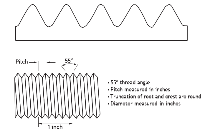
Especially precise threads are known as dry fit (or dry seal) meaning that no sealant is required for a gas-tight seal. Such threads are designed to ANSI/ASME standard B1.20.1 and are needed where a sealant would contaminate or react with the contents inside the piping (i.e., oxygen service).
Tapered threaded fittings are most commonly found in conjunction with carbon steel and other metallic pipe but are also used on plastic piping.
Due to the interference fit (wedging effect) of the tapered thread, extreme care must be used to avoid over-tightening a plastic joint. The over-stressed female fitting may split days, weeks or even years after initial installation.
|
Nominal Size |
Threads Per Inch |
Pipe OD |
Pipe ID |
Thread Angle |
Pitch |
|
[latex]\frac{1}{8}[/latex] in. |
NPT 27/ISO 28 |
0.405 in. |
0.269 in. |
60°/55° |
0.037 in./0.036 in. |
|
0.25 in. |
NPT 18/ISO 19 |
0.540 in. |
0.364 in. |
60°/55° |
0.0556 in./0.053 in. |
|
[latex]\frac{3}{8}[/latex] in. |
NPT 18/ISO 19 |
0.675 in. |
0.493 in. |
60°/55° |
0.0556 in./0.053 in. |
|
0.5 in. |
NPT 14/ISO 14 |
0.840 in. |
0.622 in. |
60°/55° |
0.0714 in./0.071 in. |
|
[latex]\frac{3}{4}[/latex] in. |
NPT 14/ISO 14 |
1.050 in. |
0.824 in. |
60°/55° |
0.0714 in./0.071 in. |
|
1 in. |
NPT 11.5/ISO 11 |
1.315 in. |
1.049 in. |
60°/55° |
0.087 in./0.091 in. |
|
1[latex]\frac{1}{4}[/latex] in. |
NPT 11.5/ISO 11 |
1.660 in. |
1.380 in. |
60°/55° |
0.087 in./0.091 in. |
|
1[latex]\frac{1}{2}[/latex]in. |
NPT 11.5/ISO 11 |
1.900 in. |
1.610 in. |
60°/55° |
0.087 in./0.091 in. |
|
2 in. |
NPT 11.5/ISO 11 |
2.375 in. |
2.067 in. |
60°/55° |
0.087 in./0.091 in. |
Steel Pipe Nominal Dimensions for Standard Weight (Schedule 40) Pipe
Pipe size is specified with two non-dimensional numbers: Nominal Pipe Size (NPS) for diameter (based on inches) and pipe schedule (Sched. or Sch.) for wall thickness. Nominal Pipe Size (NPS) is loosely related to the inside diameter of Schedule 40 pipe. NPS is used for referencing pipe sizes from 3 mm ([latex]\frac{1}{8}[/latex] in.) through 30 cm (12 in.), respectively.
Because of the pipe wall thickness, the actual diameter of the threads is larger than the NPS. Other schedules of pipe have different wall thickness, but the OD and thread profile remain the same, so the inside diameter of the pipe is therefore different from the “nominal” diameter.
Most threads are right hand, which means the fitting is screwed on to the threaded pipe in a clockwise motion. Other threads are left hand, in which case the fitting is screwed onto the threaded pipe with a counter-clockwise motion. Unless a thread is designated otherwise, it is assumed to be right hand.
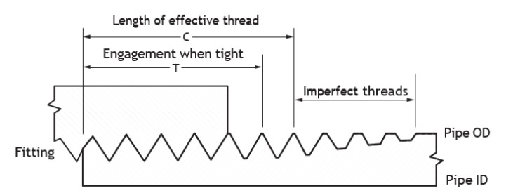
Considering that 7 to 8 threads are engaged when a pipe is screwed to a fitting (a few more for pipe sizes larger than 32 mm (1[latex]\frac{1}{4}[/latex]in.), the approximate thread engagement can be measured or calculated for the various sizes of pipe. This will be useful in determining the length of pipe to cut when the centre-to-centre measurement between two fittings is known.
Pipe Taps
Pipe taps are used to cut or repair internal pipe threads. The process is called tapping and is usually done by hand, using a special wrench to hold and turn the tap.
The pipe tap cuts standard tapered internal pipe threads. The diameter and pitch are usually stamped on the shank (shaft) of the tap.
The flutes (grooves) on a tap provide a space between the cutting edges to catch metal chips. The square end of the tap provides a sturdy grip for the tap wrench. Before attempting to tap new threads in a bare hole, taper the hole (with a taper pipe reamer) to properly shape the hole.
Pipe Dies
Dies are used to cut the external threads on pipe and fittings. The process is known simply as threading. A die head holds the cutting dies in place. A handle is mounted on the die head, often with a ratchet assembly for convenience and ease of operation and then turned to form the threads.
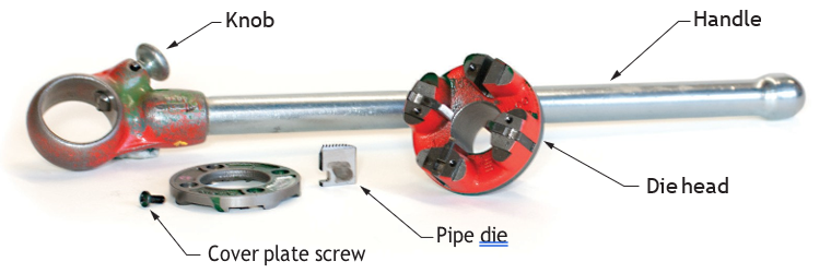
Dies have flutes or spaces between the cutting edges to provide space for metal chips to escape during the threading operation. They also have an angle notched into the front of the die, called the lead angle, which allows the dies to start easily on the work piece.
There are two main types of dies, full width dies and receding
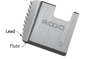
Full Width Dies
Full width dies are equal to the length of the thread to be cut. The die moves along the pipe as it cuts the thread, and when the outer edge of the die is flush with the end of the pipe, the thread is complete. This applies to taper threads only. Full-width dies are used for threading smaller pipe sizes, where less effort is required.
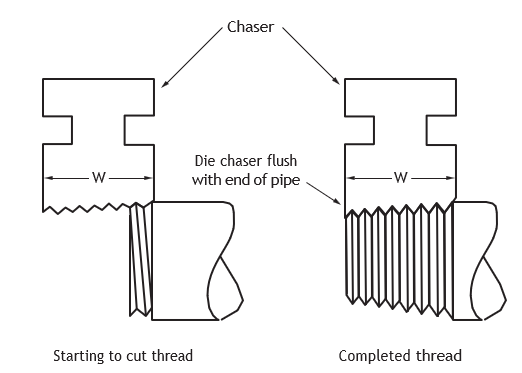
Receding Dies
Receding dies have considerably less width than the length of the thread to be cut. The die must travel along the pipe to cut the thread, and as the die moves along the pipe, it must recede from the centreline of the pipe in order to cut a tapered thread.
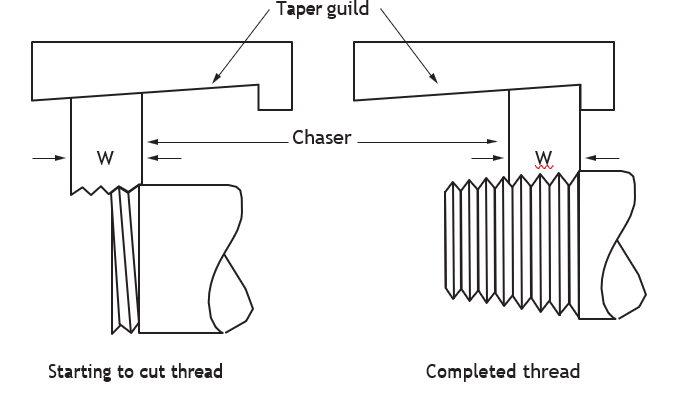
Receding dies are usually used to thread larger pipe where there is considerable surface area to cut.
Hand Threaders
The ratchet type of threader is preferred to other hand methods because the worker’s body weight can be used to turn the full width dies while standing to one side of the pipe.
Drop head threaders are quick and easy to use for small jobs or in close quarters. The dies are interchangeable between similar pipe pitches.
Exposed Ratchet Drop Head Threader
The exposed ratchet drop head threader may be more widely used than the enclosed type. It is designed for pipe sizes ranging from 3 mm to 5 cm ([latex]\frac{1}{8}[/latex] in. to 2 in.). The die head locks into the ratchet and handle assembly and is removed by pulling out the reversible ratchet knob.
Enclosed Ratchet Drop Head Threader
With the enclosed ratchet drop head threader, the die head snaps into the ratchet from either side and is easily removed by pushing it out from the body. The ratchet is enclosed within the head of the ratchet handle. The pipe size capacity of this style is from 3 mm to 32 mm ([latex]\frac{1}{8}[/latex] in. to 1[latex]\frac{1}{4}[/latex] in.).
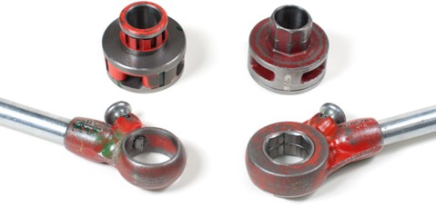
In both the exposed and enclosed models, the dies can be reversed when threading in tight locations.
Drop head threaders can also be used with power vises (a machine used for turning pipe).
Jam-proof Ratchet Threader
The jam-proof ratchet threader uses receding dies and is useful for threading pipe between 2.5 cm to 5 cm (1 in. to 2 in.) in size. It uses one set of dies to thread different pipe sizes, and it is “jam-proof” (meaning that it will kick out automatically to prevent damage caused by dies receding past their limit after the thread is completely cut). This hand threader is often used as an attachment on power vises.
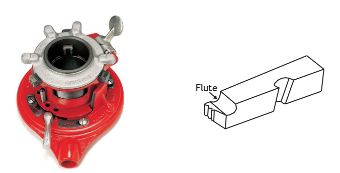
Geared Pipe Threader
The geared pipe threader is mainly used with a power vise. It uses one set of high-speed dies for threading several sizes of pipe. A selector plate quickly sets the dies and work holder to the desired pipe size. By making adjustments, the geared threader can cut straight or tapered threads, as well as oversized or undersized threads.
The Model 141 geared threader cuts threads for pipe sizes 6 cm to 10 cm (2[latex]\frac{1}{2}[/latex] in. to 4 in.) and the Model 161 threads 10 cm to 15 cm (4 in. to 6 in.) steel pipe.
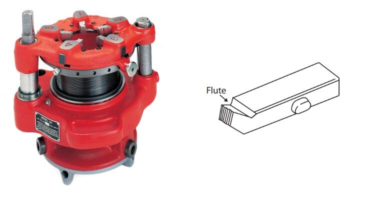
Geared threaders can be driven by hand with a ratchet handle (not recommended), or by power equipment.

A stationary power drive can be equipped with a drive shaft to power the geared threader, and there is also a hand-held power attachment available.
Thread Cutting Oil
To produce accurate work and smooth cuts, thread cutting oil (mineral oil) is used during a threading operation. The oil covers the pipe and the dies to reduce friction, cool both the chasers and the pipe, and flush away metal chips.
Thread cutting oils are either clear or dark and produce the same result when working with either power-driven or hand tools. The important ingredients include:
- Fatty oil to provide an even covering film on the workpiece
- Sulphur to supply a tough chemical film between the cutting edges and the threaded material
- Anti-foam agent to reduce surface tension and foam build-up
- Germicide to lessen the risk of infection should the operator be injured
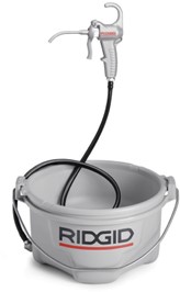
Thread cutting oils should not be confused with the oils used to maintain the condition of tools. They are not meant to be used as lubricants for moving parts or machinery.
The hand-powered oiler provides the flow of oil to the workpiece and chasers during the threading operation. It contains a screened sump to receive oil, chips and materials, plus a hand-operated pistol-style pump to supply the oil as needed.
Occasionally the chip tray needs to be emptied of scrap material and the oil level should be maintained as directed by the manufacturer. Deal with the disposal of chips, metal scraps and used oil accordingly. Consult your site supervisor for an approved disposal location.
Roll Groovers
Roll grooving is a piping connection method that continually grows more in popularity. Using pressure on a set of rollers that track the circumference of the pipe, grooves are formed to match strict specifications.
Using matching fittings and shoulder-style couplings with a gasket, grooved joints can be found in fire sprinkler systems, heating and cooling distribution, and water mains.
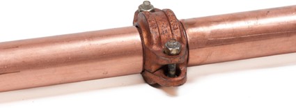
Hand-operated roll groovers are ideal for in-place field applications. Some models require only 89 mm (3[latex]\frac{1}{2}[/latex] in.) of clearance to travel around a pipe and a minimum of only about 76 mm (3 in.) of exposed pipe for grooving. With the appropriate roll sets, they can form grooves in the walls of many types of metallic pipe up to 30 cm (12 in.) in diameter. A must when performing service work, the hand-operated groover is available in several different styles. Most employ the use of a ratchet handle and can be adapted for use on a power vise as well.
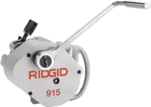
Check Your Knowledge: Tubing Benders and Hand Threading Tools
Complete the Complete the interactive knowledge test below.
If you are using a printed copy, you can scan the QR code with your digital device to go directly to the interactive knowledge test.

Electrical Testing Equipment
A technician is only as accurate as the measurement equipment being used. If the equipment is used incorrectly or is faulty, then the measurements will be inaccurate. If the measurements are inaccurate, then the technician will draw the wrong conclusions. To avoid getting inaccurate readings, you need to handle, use, and store meters properly.
The two major types of meters are digital and analog. Although both meters perform the same functions, they look different. As you can see, the difference is in the display unit.
Digital meters are usually simpler to use and are more accurate than analog meters and therefore have become more popular. We will focus on the digital multimeter (DMM), as it is the most common type in use, although analog multimeters may still be preferable in some cases, for example when monitoring a rapidly varying value.
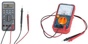
Meter Safety Precautions
The proper care of test equipment and instruments is of utmost importance, whether they are analog or digital. The length of time an instrument retains its original usefulness, and accuracy depends largely on the care it receives in the hands of the user.

Improper connection can cause damage to the circuit or the test instrument and cause personal injury.
Precautions in Handling and Using a Meter
These precautions apply equally to digital and analog meters.
- Do not drop any meter.
- Do not overload any meter. When in doubt, use a high range that you know will not be overloaded. You can always switch to a lower range if necessary.
- Do not tamper with precision instruments. Let a competent instrument repair person service precision instruments.
- Before you connect a meter to a circuit, ensure that the range switch is set to an appropriate position.
- Carefully check circuit connections before applying power to meters.
- Be careful not to touch any other electronic components within the equipment.
- Be careful not to touch the probe tips to each other while connected to anything else.
Digital Multimeters
All digital multimeters combine the features of an ammeter, a voltmeter, and an ohmmeter. Figure 160 shows a typical DMM, although different models may have a different number of digits in the display unit and the input/output jacks may be in slightly different places. Since a DMM is an important tool, you will want to learn how to use one correctly
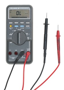
The upper portion of the DMM houses the display unit. The middle portion of the DMM houses the function switch, and the bottom portion contains the jacks for test leads.
The function dial normally has positions that will allow a technician to measure AC volts, DC volts,
DC amps, and resistance. In addition, some DMMs have function switch positions that will allow a technician to measure AC amps and to test diodes and capacitors. Some DMMs require manual setting of ranges; others have an auto-ranging feature.
All DMMs may be used to measure voltage, current, and resistance. More advanced DMMs may measure frequency, relative power differences, or other important circuit parameters. Each measurement function has similarities and differences that you need to learn about.
Many meters will use symbols on the display, switch, and connections. Table 2 lists some of the common symbols you may see:
 AC AC |
 Low Battery Low Battery |
 DC DC |
 Manual range or automatic touch hold Manual range or automatic touch hold |
 Ohms Ohms |
 Continuity beeper Continuity beeper |
 AC or DC AC or DC |
 Diode Diode |
| Hz Hertz |  Ground Ground |
| + Positive |  Fuse Fuse |
| – Negative |  Double Insulation Double Insulation |
| μF MicroFarad |  Capacitor Capacitor |
| m Milli | OL Overload |
| M Mega |
Mechanical Gauges
Analog Gauges
Gauges used for pressure testing may need to be of a type that can be calibrated—either by using a gauge tester or by comparison to a master gauge. These gauges are generally of the Bourdon tube type. The size of the dial face may be specified in the contract documents for the job. The accuracy of a manual reading increases with the size of the dial face.
The materials from which the gauge is constructed must be compatible with both the test fluid and the surrounding environment.
Bourdon Tube Gauges
The Bourdon pressure gauge uses the principle that a flattened tube tends to straighten or regain a more circular form in cross-section when pressurized (internally). Although this change in cross-section may be hardly noticeable, the strain of the material of the tube is magnified by forming the tube into a C-shape, so that the entire tube tends to straighten out or uncoil as it is pressurized. Eugene Bourdon patented his gauge in France in 1849, and it was widely adopted because of its superior sensitivity and accuracy.
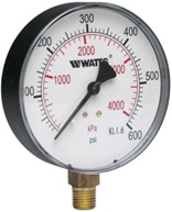
Gauge stems (sockets) may be 6 mm or 13 mm ([latex]\frac{1}{4}[/latex] in. or [latex]\frac{1}{2}[/latex] in.) NPT, depending on the pressure range.
Severe vibration or rapid fluctuations in pressure may cause gauges and recorders to give inaccurate readings. Circumstances may require the use of special devices or attachments to protect the gauge. Oil-filled gauges may be used on lines where vibration is not too severe. If pipe vibration is too severe, the gauge may have to be remotely mounted on a board and connected with a tube or hose to the test point.
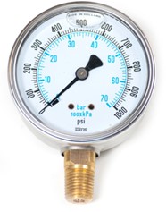
Pulsation dampeners and snubbers (Figure 164) are devices that can be installed immediately upstream of a gauge to prevent damage due to pressure pulsation or pressure surge.
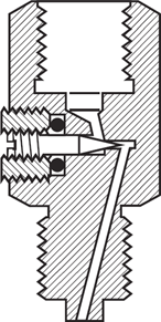
Compound Gauges
A compound gauge indicates pressures above atmospheric (in psi) and vacuum pressures (inHg).
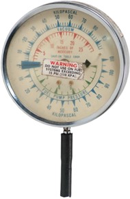
Digital Gauges
Most digital gauges have precision within ±0.25% full scale accuracy and often measure positive, negative or differential pressures. The digital displays reduce the potential for errors in readings by eliminating errors commonly experienced with the inaccuracy of analog gages. Most units are powered by 12-24 DC and often have recharging capabilities as well. Keypads allow easy access to features including backlights, peak and valley readings, auto-zero and instant conversion of pressure units. Memory functions enable storage of multiple readings and often a HOLD key freezes the current pressure for situations where readings may fluctuate.
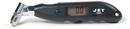
Manometers
The manometer is a measuring tool used to compare two different pressures, most commonly a system pressure and atmospheric pressure. There are two types of manometers, fluid-filled analog and digital. The analog manometer is simple, accurate, and reliable for measuring system fluid pressures. The analog manometer has no moving parts and does not require calibration. However, different fluids used such as mercury enable measurements of higher pressures but require further calculations.
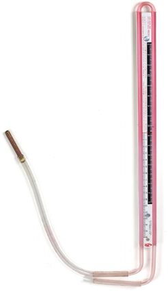
Typically, an analog manometer is a u-shaped tube partially filled with liquid, such as water or mercury. One end of the tube is open to atmosphere (P²) while the other end of the tube connects to the system in question (P¹) (Figure 168). When the system pressure acts upon the fluid, this force causes the levels in the manometer to change, as seen in the image below. By measuring the difference in levels, the technician accurately measures the system’s gauge pressure. For example, if ‘h’ was 3.0 inches in length, the system pressure is 3.0 in. of water column. If the fluid were mercury, with a specific gravity of 13.6, this measurement would read 40.8 in. of water column (1.46 psig), or 13.6 times the measurement with water.
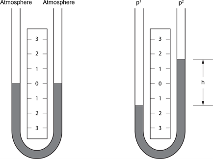
The digital manometer has some advantages over the fluid-filled analog manometer: data storage to record multiple readings; multiple setting for higher pressures; technological compatibility for uploading data.
Supplementary Videos
The following BCcampus playlist includes short demonstrations of hand tools and equipment used in the trades. These videos were created by Camosun College to support the Trades Access Common Core – Tools and Equipment OER and provide practical examples of the tools discussed in this chapter.
Watch the playlist: Tools and Equipment Videos – BCcampus [Playlist] by Camosun College
 Self-Test B-1.1: Describe Hand Tools Used in the Pipe Trades
Complete Self-Test 1.1 and check your answers.
If you are using a printed copy, please find Self-Test B-1.1 and Answer Key in the Appendix at the end. If you prefer, you can scan the QR code with your digital device to go directly to the interactive Self-Test.

References
BC Industry Training Authority. (2019). Piping trades apprenticeship program: Use Tools and Equipment—Level 1 harmonized [Binder]. Crown Publications, Queen’s Printer for British Columbia. https://www.crownpub.bc.ca/Product/Details/7960000261_S
Camosun College. (2019). Line C: Tools and Equipment—Competency C-1: Describe Common Hand Tools and Their Uses (Rev. ed.) [Learning guide]. BCcampus. https://collection.bccampus.ca/resource/BzEe9fcq/
Camosun College. (2015). Trades Access Common Core Competency C-1: Describe Common Hand Tools and Their Uses. Victoria, B.C.: Crown Publications. Download for free from the B.C. Open Textbook Collection (https://open.bccampus.ca/browse-ourcollection/find-open-textbooks/).
Camosun College. (2022). Tools and Equipment Videos [Video playlist]. BCcampushttps://media.bccampus.ca/playlist/details/0_3g8xp22x/categoryId/175673
Media Attributions
All figures are sourced from Industry Training Authority (2019) and/or Camosun College (2019) and are used under the Creative Commons Attribution 4.0 (CC BY 4.0) licence unless otherwise noted. Images copyrighted by the BC Industry Training Authority are licensed under a Creative Commons Attribution-NonCommercial-ShareAlike 4.0 (CC BY-NC-SA 4.0) licence.
All RIDGID tool images are used with permission from Emerson Professional Tools. Some of these images may have been carried forward from SkilledTradesBC learning resources; however, permission has been obtained directly from Emerson Professional Tools for their use here.
- Figure 2 Compass saw is by Cassells’ Carpentry and Joinery on Wikimedia and is in the Public Domain.
- Figure 130 Robertson screwdriver, by Vijesh Panchal on Pixabay is used under the Pixabay Content License.
- Figure 131 Phillips screwdriver, by kjpargeter on Freepik is used in alignment with the Freepik Terms of Use.
- Figure 132 Ratchet screwdriver, by Pittigrilli on Wikimedia commons, is used under a CC BY 4.0 license.
- Figure 136 Allen screwdriver, by Ralph on Pixabay is used under the Pixabay Content License.
A process in which metal is heated and then cooled in a controlled way to make it stronger, harder, or more durable. (Section B-1.1)
A type of saw blade that has been heat-treated so that the entire blade is hardened. This makes the blade very strong and resistant to wear, but also more brittle and less flexible than blades that are hardened only at the teeth. (Section B-1.1)
The distance between corresponding points on adjacent threads, often measured as threads per inch (imperial) or millimetres (metric). (Section B-1.1)
A hand saw used to cut across the grain of wood. It has special teeth designed to slice through wood fibres. (Section B-1.1)
A hand saw used to cut along the grain of wood. Its teeth are shaped to remove wood fibres as it cuts. (Section B-1.1)
The width of material removed by a cutting tool such as a saw blade. (Section B-1.1; Section B-2.2)
A spiral ridge formed on a bolt, screw, or pipe used for fastening or sealing. (Section B-1.1)
The narrow-pointed section at the end of a file that fits into the handle. (Section B-1.1)
Steel that has been heat-treated to increase hardness and durability. (Section B-1.1)
A slanted or angled edge cut into a material, often used to prepare surfaces for cutting, joining, or welding. (Section B-1.1)
A surface that has been precisely shaped or smoothed by a machine. (Section B-1.1)
A beveled edge that removes the sharp corner of a material, usually to make assembly easier or safer. (Section B-1.1)
A rough edge or small metal fragment left on a material after cutting, drilling, or machining. (Section B-1.1)
Thin-walled pipe used to transport fluids or gases. (Section B-1.1)
A device used to hold materials together, such as a nail, bolt, or screw. (Section B-1.1)
A cut made at a 90-degree angle to the length of a pipe or material. (Section B-1.1)
A mechanical tool used to securely hold a workpiece during cutting, drilling, or assembly operations. (Section B-1.1)
A cutting problem that occurs when a pipe cutter does not stay in a straight line around the pipe. Instead of following the same groove, the cutter wheel gradually moves along the pipe in a spiral pattern, resulting in an uneven or angled cut that is not square to the pipe; sometimes referred to as a barber’s pole. (Section B-1.1)
Using a long tool or handle to multiply force. (Section B-1.1)
level: Perfectly horizontal or flat, from side to side; or
level (or levelling rod): A long measuring rod used with an optical or laser level to measure height differences and determine elevations on a job site. The rod has marked scales that allow workers to read measurements from a distance.. (Section B-1.1)
A precision tool used to enlarge, smooth, or finish an existing hole or pipe end to an accurate diameter. (Section B-1.1)
The process of removing burrs or rough edges from metal, plastic, or other materials after cutting or drilling. (Section B-1.1)
A spiral ridge cut into the end of a pipe so it can screw into another pipe or fitting. (Section B-1.1)
The process of spreading the end of a pipe or tube outward so it can connect securely to a fitting. (Section B-1.1)
The process of cutting or filing the sharp edge of a pipe or material at an angle to make it smoother and easier to join. (Section B-1.1)
A seal placed between two surfaces to prevent leaks. (Section B-1.1)
A printed chart on some pipe layout tools that helps workers find angles and measurements when laying out cuts or fittings on pipe. It uses tangent values to calculate distances needed for accurate pipe layouts. (Section B-1.1)
An L-shaped measuring tool used to check right angles (90°) and lay out lines on materials such as wood, metal, or pipe. It has two straight arms set at a right angle and is commonly used for measuring, marking, and squaring workpieces. (Section B-1.1)
A measuring tool used to check right angles (90°) and measure distances. It has a ruler and an adjustable head. (Section B-1.1)
A straight measuring tool made of steel that is used to measure short distances and draw straight lines. It usually has markings in millimetres and inches for accurate measurements. (Section B-1.1)
The adjustable head of a combination square that is used to check or mark 90° (square) and 45° angles. It often includes a small spirit level and a scriber for marking lines. (Section B-1.1)
A joint made between two pieces of wood or other material at an angle of 90°, such that the line of junction bisects this angle. (Section B-1.1)
A tool used to check if something is level or plumb. It has a small bubble inside a liquid-filled tube. (Section B-1.1)
A sharp, pointed tool used to scratch or mark precise lines on metal or other hard materials before cutting, drilling, or machining. (Section B-1.1)
An attachment used with a combination square that helps find the exact centre of round objects, such as pipes or rods. (Section B-1.1)
A solid piece of metal shaped like a cylinder (round bar) that is used to make parts or components. It is often measured, cut, or machined in metalworking and pipe trades. (Section B-1.1)
An attachment used with a combination square that helps measure and mark angles. It is marked in degrees so workers can lay out accurate angles. (Section B-1.1)
A measuring tool used to identify the size and spacing of threads on bolts, screws, or pipes. It helps determine the thread pitch so the correct fastener or fitting can be used. (Section B-1.1)
A handheld measuring tool used to check the concentration of liquids, such as antifreeze, by measuring how light bends (refracts) when it passes through the liquid. (Section B-1.1)
A measurement that describes how much light bends when it passes through a substance, such as a liquid or glass. It is used to help determine the concentration or composition of a liquid. (Section B-1.1)
A measuring tool used to check the density of a liquid. It floats in the liquid, and the level where it sits shows the liquid’s density or concentration. (Section B-1.1)
A scientific rule that explains why objects float or sink in liquids. It states that an object in a liquid is pushed upward by a force equal to the weight of the liquid it displaces. (Section B-1.1)
A straight tool used to check whether a surface is level (horizontal) or plumb (vertical). It usually contains glass tubes with bubbles that show when something is straight. (Section B-1.1)
A small, compact level used to check level, plumb, or 45° angles in tight spaces where a longer level will not fit. (Section B-1.1)
A small level that hangs on a string line to check if the line is level. It is used for rough measurements such as setting fence posts or checking building lines. (Section B-1.1)
A pointed weight attached to a string that is used to find a perfectly vertical (plumb) line. When the weight hangs freely, the string shows a straight up-and-down direction. (Section B-1.1)
The weighted end of a chalk line tool that helps keep the string tight and straight. It allows workers to snap a straight chalk line on a surface for marking and layout. (Section B-1.1)
Perfectly vertical or straight up and down, like the direction gravity pulls. (Section B-1.1)
Also known as 4-pin level; a surveying instrument with a telescope used to measure height differences and establish level reference points over long distances on construction sites. (Section B-1.1)
A tool that projects a straight beam of light to create a level or vertical reference line. It helps workers align pipes, walls, or other structures accurately. (Section B-1.1)
A soft, chalk-like material used to mark lines on metal or other surfaces, especially in welding or metalworking. The marks are easy to see and can be wiped off after the work is finished. (Section B-1.1)
Lines drawn on material to guide cutting, drilling, or shaping operations. (Section B-1.1)
A marking tool that uses a chalk-covered string to create long, straight lines on surfaces such as wood, metal, or concrete. The string is stretched tight and snapped against the surface to leave a straight chalk mark. (Section B-1.1)
A tool with two sharp points used to draw circles or measure distances on metal or other materials. (Section B-1.1)
A curved line that is part of a circle. (Section B-1.1)
The exact middle point of a circle or round object. (Section B-1.1)
Adjustable points attached to a bar or ruler that are used to draw very large circles or arcs. (Section B-1.1)
A pointed tool used to make a small dent in metal so a drill bit will start in the correct place. (Section B-1.1)
A very sharp punch used to mark precise points on metal before drilling. (Section B-1.1)
The material or object being worked on, such as metal, pipe, or wood. (Section B-1.1)
The hardness and strength created in metal by heat treatment. (Section B-1.1)
Using leverage with a tool to separate or lift materials apart. (Section B-1.1)
Steel that is shaped using heavy pressure and heat to make it stronger. (Section B-1.1)
A very strong hardwood commonly used to make tool handles. (Section B-1.1)
How the weight of a tool is distributed, which affects how comfortable and controlled it feels in the hand. (Section B-1.1)
A hammer with a flat striking face on one side and a rounded ball-shaped end (peen) on the other; commonly used in metalworking for shaping metal, setting rivets, and striking tools such as chisels or punches. (Section B-1.1)
A curved outward shape. (Section B-1.1)
The rounded end of a hammer head opposite the striking face. (Section B-1.1)
A metal pin used to permanently fasten materials together. (Section B-1.1)
Steam tracing: A method of using steam pipes to keep other pipes warm so fluids do not freeze.
Steam-tracing tubing: Small tubing that carries steam along a pipe to keep the pipe and its contents warm, helping prevent liquids from cooling, thickening, or freezing. (Section B-1.1)
A hammer designed to reduce rebound when striking a surface. (Section B-1.1)
A tool used in welding to chip and remove slag from a weld after the metal has cooled; usually has a pointed tip and a chisel edge to reach tight areas around the weld. (Section B-1.1)
A hard residue left on a weld after metal is melted and fused together. (Section B-1.1)
(also called a gooseneck); A heavy metal bar used for prying materials apart and pulling nails during construction or demolition. (Section B-1.1)
The process of breaking down or removing structures. (Section B-1.1)
Temporary structures used to shape concrete while it hardens. (Section B-1.1)
(also called the crowbar or long bar); A long, strong metal bar used to lift, pry apart, or move heavy materials. (Section B-1.1)
A protective pipe or opening that allows another pipe to pass through walls or structures. (Section B-1.1)
A small flat metal prying tool with claws on both ends used for light prying and nail removal. (Section B-1.1)
(also called cat's paw); A short metal bar with a claw-shaped end used to pull nails out of wood. (Section B-1.1)
Jaws with small teeth or ridges that help grip an object so it does not slip. (Section B-1.1)
A vise used on machines such as drill presses to hold a workpiece firmly while it is being drilled or cut. (Section B-1.1)
A clamp shaped like the letter “C” that is used to hold pieces of material tightly together or to hold something to a table while working. (Section B-1.1)
A tool used to hold a pipe steady while it is cut, threaded, or worked on. (Section B-1.1)
A portable pipe vise with three legs and a chain used to hold pipes firmly at a job site. (Section B-1.1)
A vise designed to hold long pieces of pipe from one side while work is done on them. (Section B-1.1)
A portable pipe vise with three legs and a chain used to hold pipes firmly at a job site. (Section B-1.1)
A portable vise with three legs and metal jaws used to clamp and hold pipes while they are being worked on. (Section B-1.1)
A portable pipe vise mounted on a stand with legs that support long pieces of pipe during work. (Section B-1.1)
A twisting force applied to a fastener or tool. (Section B-1.1)
A short, heavy wrench designed to tighten or loosen large nuts and bolts. It has a thick handle end that can be hit with a hammer to apply extra force when turning stubborn or tightly fastened parts. It is commonly used in heavy construction and industrial work. (Section B-1.1)
A tool used to tighten nuts or bolts to a specific amount of turning force (torque); works with a ratcheting handle so the user can tighten a fastener without removing the tool after each turn. When the correct torque is reached, the wrench usually clicks or releases to prevent over-tightening. (Section B-1.1)
A heavy tool used to grip and turn pipes. It has adjustable jaws with teeth that hold tightly onto round pipe. (Section B-1.1)
A type of pipe wrench with a flat hammering surface used to loosen stuck pipes or fittings. (Section B-1.1)
A classic pipe wrench design invented by Daniel Stillson that uses adjustable serrated jaws to grip pipes. (Section B-1.1)
A wrench with a spring-loaded jaw that allows quick gripping and ratcheting with one hand. (Section B-1.1)
(also called monkey wrench); A wrench used in construction that has a pointed end to help align holes and a wrench end to tighten bolts. (Section B-1.1)
A tool used to tighten or loosen pipes or fittings that have six flat sides (a hexagonal shape). The wrench fits around the flats of the pipe fitting so it can grip firmly and turn the pipe without slipping. It is commonly used when working with hex-shaped pipe fittings and valves. (Section B-1.1)
A wrench that uses a metal chain to wrap around and grip a pipe so it can be turned. (Section 1.1)
A tool that uses a chain wrapped around a pipe to grip and turn the pipe when tightening or loosening it. (Section 1.1)
A wrench that uses a rubber or fabric strap to grip and turn round objects without damaging them. (Section B-1.1)
A special wrench with a long handle used to tighten or loosen nuts in hard-to-reach places, such as under sinks. (Section 1.1)
A basin wrench designed specifically for tightening or loosening plastic nuts under sinks. (Section B-1.1)
A tool used to grip and turn parts from inside a pipe or fitting. (Section B-1.1)
adjustable pliers used to grip, hold, or turn objects. The jaws can be moved to different positions using a curved slot (arc joint), allowing the tool to open wider or narrower depending on the size of the object being held. They are commonly used for gripping pipes, nuts, and other parts in plumbing or mechanical work. Many trades people refer to these as Channellock pliers. (Section B-1.1)
adjustable pliers used to grip and turn pipes, fittings, and other round objects. The jaws can be moved to different positions to fit different sizes, and the teeth help hold the object tightly without slipping. They are commonly used in plumbing and mechanical work. (Section B-1.1)
Strong pliers used for gripping, twisting, bending, and cutting wire. They have short jaws with flat gripping surfaces and sharp cutting edges near the pivot. These pliers are commonly used by electricians when working with electrical wires and cables. (Section B-1.1)
Pliers with long, narrow jaws that taper to a point. They are used to grip, bend, and hold small objects or wires, especially in tight or hard-to-reach spaces. These pliers are commonly used in electrical work, crafts, and small mechanical repairs. (Section B-1.1)
Tools used for cutting wire and small metal pins. The cutting edges are set at an angle near the pivot, which allows the user to cut close to a surface or in tight spaces. These pliers are commonly used in electrical and mechanical work. (Section B-1.1)
(Often referred to as vice-grips); adjustable pliers that can clamp tightly onto an object and stay locked in place until released. A screw on the handle adjusts the jaw opening, and a locking mechanism holds the pliers closed. They are commonly used to grip, clamp, or hold parts securely during mechanical or repair work. (Section B-1.1)
A method of joining pipe or tubing by squeezing a metal ring or fitting tightly around it with a special tool. (Section B-1.1)
a tool used to tighten or loosen screws that have a star-shaped pattern with six points in the head. The shape helps the screwdriver grip the screw firmly, reducing slipping and allowing more turning force. Torx screwdrivers are commonly used in electronics, automotive work, and machinery. (Section B-1.1)
A tool used to tighten or loosen screws that have a star-shaped pattern with six points in the head. The shape helps the screwdriver grip the screw firmly, reducing slipping and allowing more turning force. Torx screwdrivers are commonly used in electronics, automotive work, and machinery. (Section B-1.1)
When a screwdriver slips out of the screw head while turning it. This can damage the screw head and make the screw harder to tighten or remove. (Section B-1.1)
A tool used to tighten or loosen screws that have a clutch-shaped slot in the head. The screwdriver tip fits the special slot so the screw can be turned without slipping. These screws are often used in equipment and machinery. (Section B-1.1)
A condition where metal has been softened by exposure to high heat. When wire rope becomes annealed, it loses strength and hardness, making it unsafe for lifting or rigging operations. (Section B-4.5)
Tools used to bend metal tubing or pipe into smooth curves without flattening or damaging the tube. They help create accurate angles and shapes when installing plumbing, heating, or mechanical tubing. (Section B-1.1)
A process used to change the shape or size of a pipe or tube end, usually to make it fit inside another pipe. (Section B-1.1)
Cross-linked Polyethylene (PEX) is a type of flexible plastic pipe used for plumbing and heating systems. (Section B-1.1)
A thread that gradually decreases in diameter along its length to create a tighter seal as it is tightened. (Section B-1.1)
A standard type of pipe thread used in North America - ANSI/ASME standard B1.20.1. The threads are slightly tapered so they seal tightly when pipes are screwed together; sometimes still referred to as American Standard Pipe Thread (ASPT). (Section B-1.1)
When pipe parts are assembled together without using sealant, glue, or thread compound. It is usually done to check that the pieces fit properly before the final installation. (Section B-1.1)
Occurs when two parts are pressed together so tightly that they stay in place without fasteners. The tight fit creates friction that holds the parts securely together. (Section B-1.1)
A standard system used to identify the size of pipes. The number refers to the approximate inside diameter of the pipe, even though the actual measurements may vary depending on the pipe wall thickness. (Section B-1.1)
Pipe taps are cutting tools used to create internal threads inside a pipe or fitting. Tapping is the process of using a pipe tap to cut these threads so another threaded pipe or fitting can be screwed into it. (Section B-1.1)
the long, straight part of a tool that connects the working end (such as a blade or tip) to the handle. It helps transfer force from the handle to the cutting or working part of the tool. (Section B-1.1)
The long channels cut into tools such as drill bits or taps. They help remove chips of material while cutting and allow cutting fluid to reach the cutting edge. (Section B-1.1)
Cutting tools used to create threads on the outside of a pipe. These threads allow pipes and fittings to be screwed together to form a tight connection. (Section B-1.1)
the angle at which a cutting edge meets the material being cut. It helps guide the tool into the material and affects how smoothly the tool cuts and removes material. (Section B-1.1)
A tool used to cut threads onto the outside of a pipe or rod so that fittings or other threaded parts can be screwed onto it. Threaders are commonly used in plumbing and pipe installation. (Section B-1.1)
A pipe-threading tool used to cut threads on the outside of pipes; it has a ratcheting handle for use in tight spaces, and the drop head holds the cutting dies that form the threads. The exposed design allows the cutting head to be easily seen and adjusted during use. (Section B-1.1)
A pipe-threading tool that cuts threads on the outside of a pipe. It uses a ratcheting handle so the pipe can be threaded in tight spaces, and the jam-proof design helps prevent the tool from sticking while cutting threads. (Section B-1.1)
A pipe-threading tool that uses gears to help turn the cutting dies around the pipe. The gears provide extra mechanical advantage, making it easier to cut threads on larger pipes with less effort. (Section B-1.1)
A process used to form a groove around the outside of a pipe by pressing it between rolling wheels. The groove allows special couplings to be attached so pipes can be joined together without threading or welding. (Section B-1.1)
An electronic tool used to measure electrical values such as voltage, current, and resistance. It shows the readings on a digital screen and is commonly used to test electrical circuits and equipment. (Section B-1.1)
An electronic tool used to measure electrical values such as voltage, current, and resistance. It shows the readings on a digital screen and is commonly used to test electrical circuits and equipment. (Section B-1.1)
A device used to measure the pressure of a gas or liquid in a system. It uses a curved metal tube that straightens slightly when pressure increases, moving a needle on a dial to show the pressure reading. (Section B-1.1)
The threaded connectors on a pressure gauge that attach the gauge to a pipe, valve, or fitting. They allow the gauge to be securely connected so it can measure the pressure inside the system. (Section B-1.1)
Small devices attached to pressure gauges to reduce rapid pressure fluctuations. They help protect the gauge from damage and allow the pressure reading to remain steady and easier to read. (Section B-1.1)
a pressure gauge that can measure both positive pressure and vacuum in the same instrument. It shows pressure above and below atmospheric pressure on the same dial. (Section B-1.1)
A device used to measure the pressure of a gas or liquid. It often uses a tube filled with liquid, such as water or mercury, and the difference in liquid levels shows the pressure. (Section B-1.1)