B-4.2 Describe Hoisting, Lifting and Rigging Equipment
The following rigging accessories and lifting devices are commonly used in the pipe trades and must be selected and used correctly to ensure safe lifting operations.
Lifting and Hoisting Accessories
Rigging loads requires the use of various hardware items for lifting. Correct selection, inspection, and assembly of these hardware items is critical to ensuring a safe lift. Common rigging hardware includes:
- Turnbuckles
- Eyebolts
- Shackles
- Cable clips and thimbles
- Hooks
- Slings and hitches
- Spreader bars
Turnbuckles
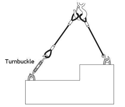
Turnbuckles are used to adjust the lengths of slings so that loads can be lifted in a level position.
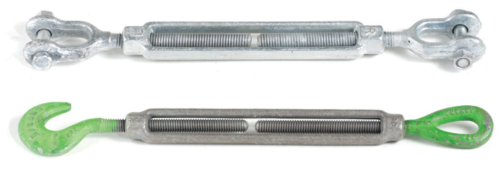
They are metal sleeves with left-hand internal threads at one end and right-hand internal threads at the other. Threaded metal rods are fitted into each end.

The ends of these threaded rods are available as eyes, jaws, or hooks. All hooks on turnbuckles must have a safety catch (Figure 3).
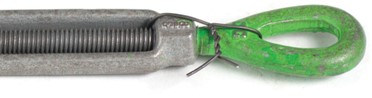
It is important to prevent turnbuckle ends from rotating. Rotation can be caused by vibration or by tension on the rope attached to the turnbuckle. If there is any chance that the ends of the turnbuckles could rotate within the sleeve, the ends should be secured to the sleeve using lock wire, as shown.
Eyebolts
Eyebolts are used to provide a secure point of attachment for hoisting operations. There are two types: shoulder and shoulderless eye bolts. Shoulderless eye bolts must not be used in overhead lifting, because force applied from the side at any angle will break the stem of the bolt.
Shoulder-type eye bolts are able to withstand pulls up to 45° from vertical, providing the pull is applied along the plane of the eye. Pulling at an angle that is not in the same plane will bend or break the eye. Always make sure that the eye bolt is properly installed so that the shoulder sits tightly against the load. Do not use an eye bolt if there is any space between the shoulder and the load, because it will act like a shoulderless eye bolt and may break under stress.
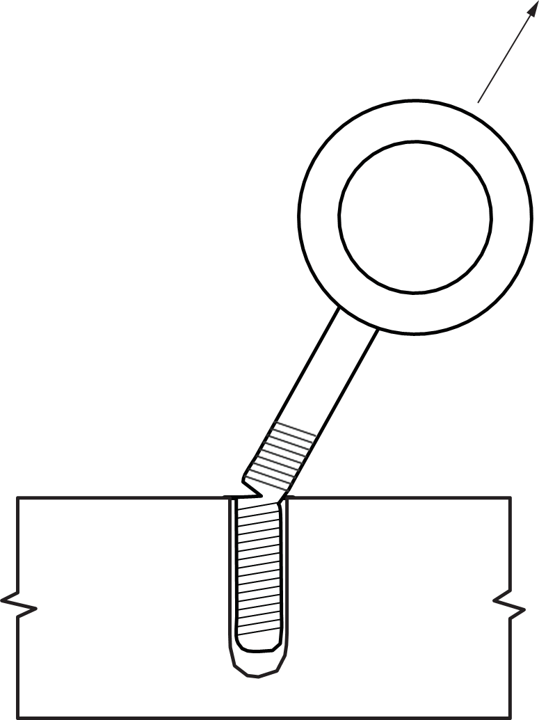
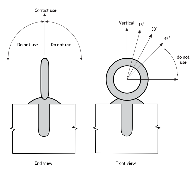
The Working Load Limit (WLL) for eye bolts are given for vertical pulls. When lifting at an angle, you must reduce the WLL of the eye bolt as follows:
- Vertical pull = No reduction in WLL
- 15° from vertical = 45% reduction in WLL
- 30° from vertical = 65% reduction in WLL
- 45° from vertical = 75% reduction in WLL
- Over 45° from vertical = NOT RECOMMENDED
Shackles
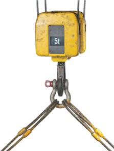
Shackles (Figure 7) are used to connect a sling to a load. They should be used whenever two or more ropes are placed over a hook (Figure 8). The shackle should have a throat large enough to avoid crowding and pinching the ropes. The working load limit (WLL) of a shackle must be shown as a stamped or embossed number on the body of the shackle. Never use shackles that do not display a load rating.
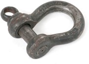
Never replace the pin of a shackle with an ordinary bolt. Shackle pins are made of hardened steel, while ordinary bolts may bend under load and damage the shackle. In many applications, the shackle pin must be secured for safety. The pin may be wired off to prevent it from turning loose, or the pin may be seized in place.
Figure 9 shows a shackle attachment that could cause the screw pin to become loose.
Never attach a shackle so that the load is applied to the sides of the shackle. This condition is called crossbow loading. Always apply the load to the pin and the curved body of the shackle. To prevent crossbow loading, never use a shackle with slings where the sling angle will exceed 45° between the two slings at the shackle.
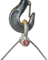
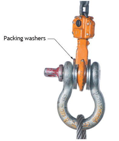
Figure 10 shows the correct method for attaching a shackle to a lifting hook. Note that if the width of the shackle’s opening is considerably greater than the thickness of the hook, packing washers should be used to centre the hook on the shackle.
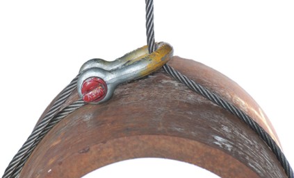
Shackles may be used to form a choker hitch, but you must make sure the pin is not bearing on any moving part of the rope. The rope could cause a screw pin to turn and become loose.
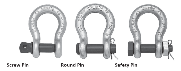
There are three basic types of pins available for shackles:
- *Screw pins
- Round pins
- Safety type pins
*The screw pin shackle is the most commonly used.
Cable Clips and Thimbles
Cable clips are used to fasten the end of a wire rope back onto its standing part to form a loop. Cable clips provide a relatively quick and easy method for tying wire rope. However, the crimping action of cable clips significantly reduces the breaking strength of wire rope (by up to 20%).
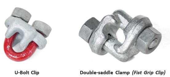
The two most popular types of cable clips are the U-bolt clip and the double saddle (fist grip) clip, shown here. The U-portion must be installed on the dead end of the rope.
The space between cable clips is usually equal to six or seven rope diameters. The distance from the rope end to the first cable clip should also be six or seven rope diameters. To figure out how many clips are required to make the loop, multiply the rope diameter by three and round up to the next whole number.
Wire rope has a tendency to stretch a small amount when first put into service. Wire rope reduces in diameter as it stretches. Tighten all cable clips after the first hour of service for a new connection. If the cable clip connection is under heavy strain, check the tightness of the nuts at regular intervals until no further loosening is observed.
The correct procedure for installing cable clips is as follows:
- Calculate the length required for the loop (number of clips required multiplied by six rope diameters). Install the first clip six rope diameters from the rope end. Tighten the nuts to the recommended torque using a torque wrench.

- Install the second clip as near the thimble as possible. Tighten the nuts securely but do not apply final torque yet.

- Install all other clips at equal spacing. Apply tension to the rope and then tighten all nuts to the recommended torque.

Correctly installed cable clips reduce the breaking strength of wire rope by approximately 20%; incorrectly installed, they can reduce the breaking strength by up to 50%.
Hooks
Hooks are commonly used to connect lifting devices to loads. Common types include:
- Standard eye hooks
- Slip hooks
- Grab hooks
- Sorting hooks
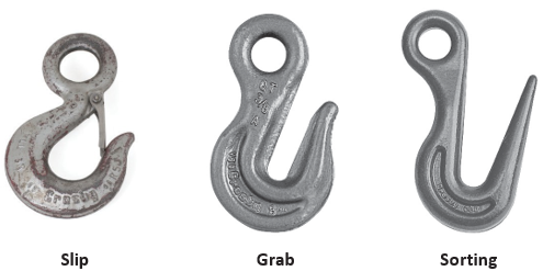
The standard safety eye hook is commonly used to lift loads that have been rigged, as is the variation that includes a swivel base.
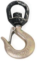
All hoisting hooks, except grab and sorting hooks, must have safety catches. Open hooks must not be used to lift a bucket, cage, or skip if there is a possibility the load could injure people.
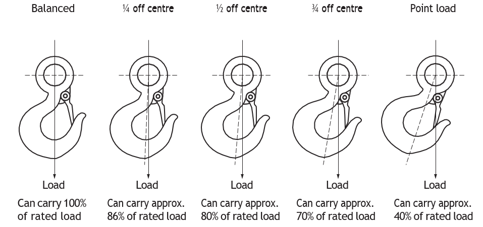
Hooks are usually made of alloy steel, and their working load limit (WLL) should be stamped on them. It is important to remember that the working load limit applies only when the load sits in the saddle of the hook. If the load is off-centre or sits between the saddle and the tip, the working load limit is significantly reduced (see illustration).
Slip and grab hooks are generally attached to the ends of chains to pick up or pull a load. Sorting hooks are also referred to as shake-out hooks and are primarily used at the end of slips for picking up steel plate and other structural shapes. The long, thin hook can slide between closely stacked steel shapes. When sorting hooks are used to lift heavy loads, you must ensure that the load sits squarely in the bottom (saddle) of the hook.
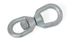
To protect chains from the stress of twisting while under load, all hoisting chains should be equipped with swivels, such as those shown here.
Choker Hooks
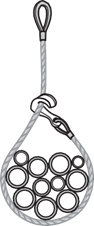
Choker hooks are fittings attached to the end of a sling. The width of the hook protects connected ropes from sharp bends. When the hook is attached back onto its sling, it forms a choker hitch.
The standard choker hook shown here is attached to the end of the sling. The sling is passed around the load, and the wide surface of the hook is hooked over the standing part of the sling.
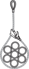
A variation of the standard choker hook, called the adjustable or sliding choker hook (below) is mounted on a sling that has a loop at each end. The sling is passed around a load, and the end loop is hooked over the choker hook.
Slings and Hitches
Most items that require hoisting have no provisions for attaching a hoisting line to them. Slings are used to connect the load to the lifting device. Slings may be made of fibre rope, wire rope, chain, or webbing, and they may be attached to loads in a variety of ways.
To protect both the load and the sling, place padding between the sling and any sharp corners on the load (called softeners). The following simplified diagrams may not show softeners being used, but they should be applied whenever possible in the field.
Identification
All slings must have an identification tag in accordance with ANSI/ASME and CSA guidelines. This tag provides the following information:
- Name of the manufacturer
- Diameter, width, and length of the sling
- Materials
- Rated load for the given type of hitch
- Lift angle upon which the load rating is based
Sling Design Factor
One must apply a safety factor of 5:1 to every lift. This is to account for overloading, abrasion, crushing, kinking, and impact loading of slings. Some engineered lifts may have safety factors of 6:1, 8:1, 10:1 or higher.
Synthetic Web Slings
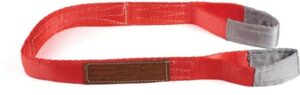
Synthetic web slings (typically made from woven nylon) are available in a variety of shapes and widths. They are softer and wider than most other slings so better protect the load against marring or scratching. The shapes most commonly found are illustrated below.
Some web slings have metal end fittings instead of sewn eyes. Two types are available (see Figure 24). A basket web sling has metal triangles of equal size at each end of the webbing. A choker web sling has a larger triangle containing a slot at one end and a smaller triangle at the other end. The smaller triangle can be passed through the slot of the larger triangle to form a choker hitch.
Metal Mesh Slings
Loads that are too abrasive or too hot for synthetic webbing yet require the wide bearing surface of a web belt are rigged with slings made of metal mesh. These metal mesh slings are usually equipped with triangle ends that permit the use of either a basket or choker hitch.
Chain
Chain slings have certain applications as they do not kink, are able to withstand rough handling, and are resistant to abrasion and corrosion. However, they have no elasticity and due to their nature, chains are less reliable than wire rope or synthetic slings and can fail without warning. The term ‘weak link’ illustrates that a single chain link can cause catastrophic failure, whereas wire rope will break progressively over time and show signs of stress or damage upon inspection.
Chain sling identification will indicate the manufacturer’s approval for hoisting. It will also show the chain’s size, WLL, length and manufacturer.
Chain slings require documented annual inspections. For a sound inspection of chain slings, clean the chain first then inspect for wear or stretching. Any stretch over 5% requires the sling to be removed from service (OHS Regulation Part 15: Rigging). Any cracks require the entire chain to be removed from service.
Rules for safe chain use include:
- Only use alloy chain slings for hoisting.
- Always use softeners for rectangular loads.
- Avoid shock loading.
- Never repair or weld links and never shorten a chain by tying a knot or bolting two links together.
- If links bind together, this indicates stretching, and further inspection is required.
- When a chain is used for a basket hitch, always hook to the master link, not the chain itself.
- Store chain in a dry place.
Identification
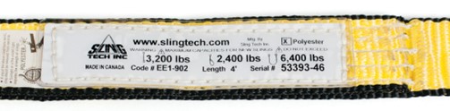
Synthetic web slings must bear an identification tag indicating the WLL (working load limit, also known as the safe working load). This tag must never be removed or tampered with.
Inspection
Web slings should be inspected for:
- Worn or distorted fittings
- Cuts
- Holes
- Punches (or punctures)
- Tears
- Frayed material
- Broken stitching
- Burns caused by acid, caustic chemicals, or heat
Inspect the slings carefully before use and make a decision about their safety. If you are not sure that the sling is safe, tag it so that it will not be used by another worker and notify your supervisor. Your supervisor should make the necessary arrangements to have the sling inspected for safety and approved before it is returned to service.

Never use a sling for lifting unless it has a tag clearly indicating its working load limit!
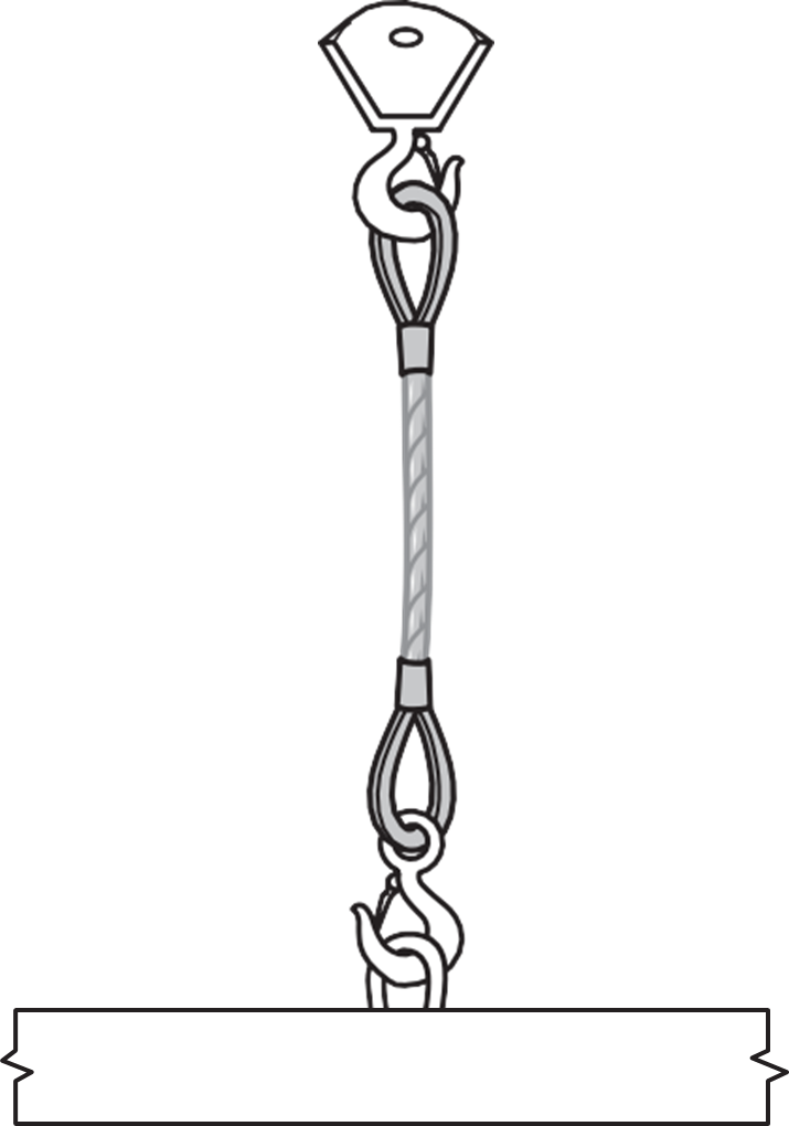
Single Vertical Hitch
The single vertical hitch consists of a single leg of sling material with a hook or an eye at each end. The eyes on fibre or wire-rope slings should be lined with thimbles to protect the strands.

Bridle Hitch
Two, three, or more legs may be used together to form a bridle hitch. Bridle hitches are generally used on loads that have suitable attachment points. To keep the load stable, the attachment points must be located above the load’s centre of gravity.
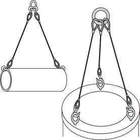
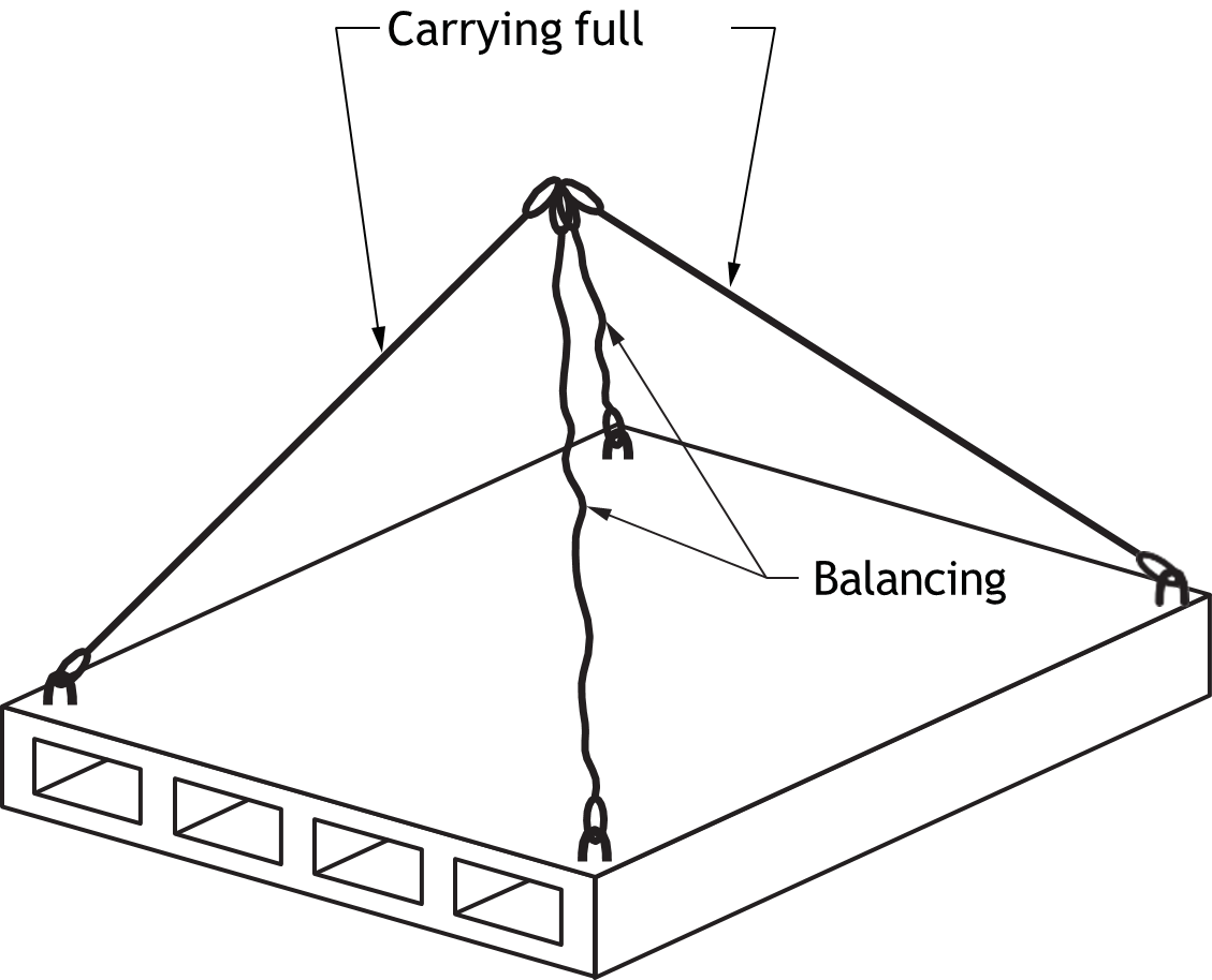
When a bridle hitch has more than two legs, do not assume that all legs are sharing the load equally. Regardless of the total number of legs, the full weight of the load might be shared by only two legs. The other legs may simply be balancing the load (see below). For this reason, each sling in a multi‑leg bridle hitch must be sized so that any one sling can safely support half of the load.
Single Basket Hitch
A single basket hitch is made from a single length of sling material passed through an opening in the load, with both ends of the sling attached to the main lifting hook.
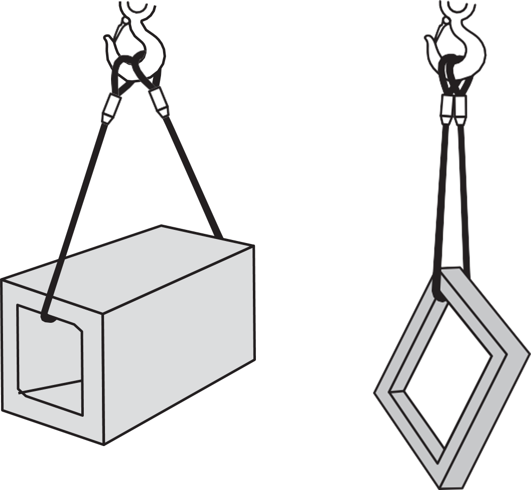
Single basket hitches must not be used on loads that could tilt or slide out of the hitch.
When a sling is wrapped around a square object, sharp corners must be padded or protected to prevent damage to both the sling and the load.
Double Basket Hitch
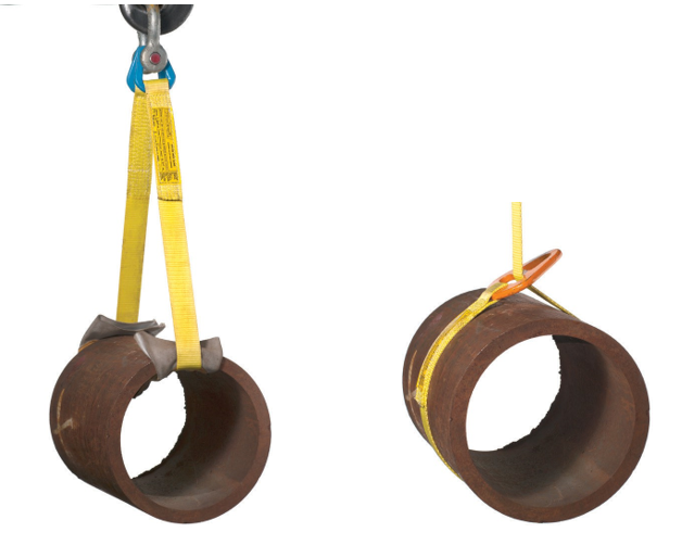
Loads that require support from underneath can be lifted with a double basket hitch. The double basket hitch must be positioned so the load is balanced between the two points of support. The two points must be far enough apart to prevent the load from tipping or sliding out of the hitch.
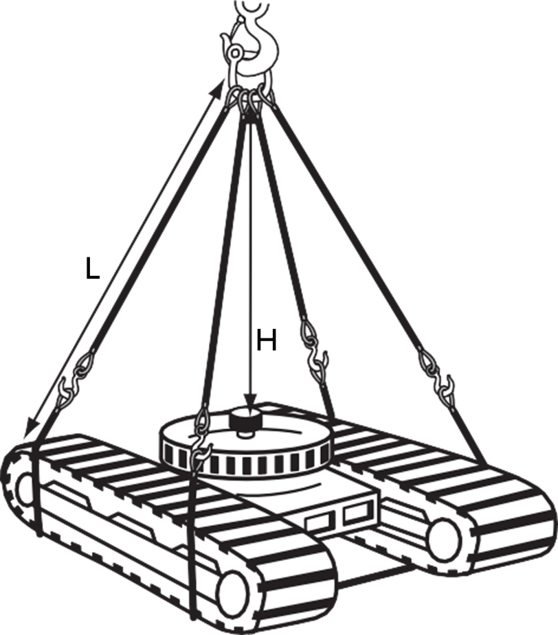
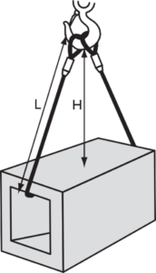
The legs of a double basket hitch should be inclined at an angle of at least 60° from the horizontal to prevent the legs from sliding toward each other. By using longer slings, you can spread the legs further apart while maintaining the 60° angle. Note that the slings may slide toward each other under load, and the load may tip out of the slings unless steps are taken to secure them in place, such as placing blocks of wood to prevent movement when lifting metal pipes.
Double-Wrap Basket Hitches
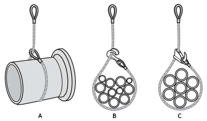
Loose loads can be securely rigged for hoisting with double basket hitches by wrapping the sling completely around the load (Figure 33). This double wrapping compresses all the components together so that even the top pieces will not slide out of the rigging.
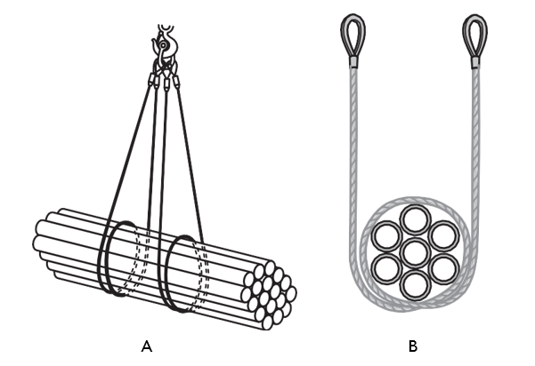
Single choker hitches (below) are made by hooking a single length of sling material back onto itself just above the load. Although there are several methods for securing the sling back onto itself, none will fully secure the top of loose loads. (see Figure 34).
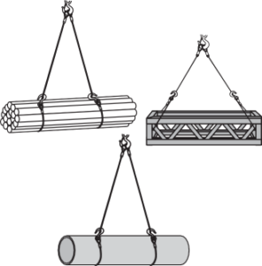
Double Choker Hitch
Double choker slings must be used on all horizontal loads made up of two or more pieces of material that are over 3 m (10 ft) in length.
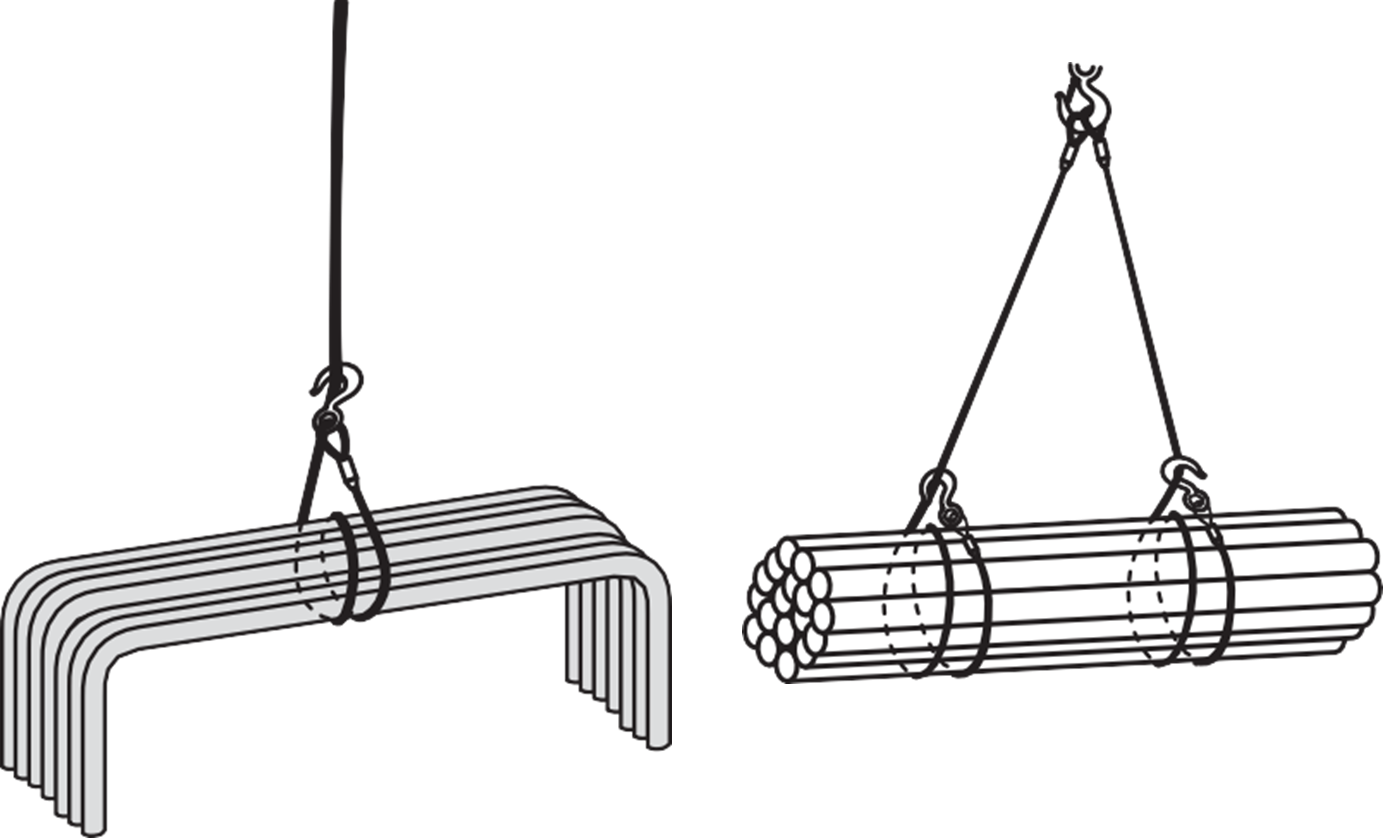
Double-Wrap Choker Hitch
The double-wrap choker hitch is similar to the double-wrap basket hitch in that both squeeze the load from all sides. Double-wrap choker hitches may be used singly or in pairs.
Endless Slings
Endless slings (also known as grommet slings) can be used in a variety of configurations. They are simply continuous loops of the same material.
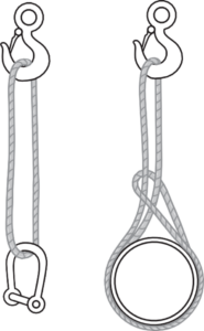
Endless slings are usually made of fibre rope or synthetic webbing. They are light to handle and do not damage the loads, but because they are subjected to sharp bends, they tend to deteriorate more rapidly than most other types of slings.
Spreader Bars
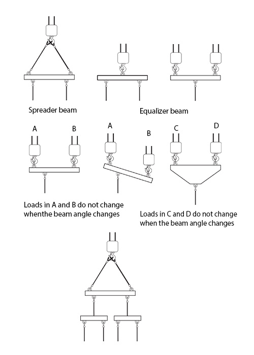
Long loads are often attached to [pb_glossary id=”5056″]spreader bars (beams)[/pb_glossary] before hoisting to prevent the load from tipping or sliding out of their rigging. Equalizer bars ensure that the load is distributed evenly between the legs of a sling or between hoist lines when more than one is used. The following figures show spreader and equalizer bars and how they are used to keep loads evenly balanced.
Equalizer bars, spreader bars, and all lifting devices must be professionally designed and manufactured. They must be certified by a registered professional engineer, stamped with the certification, and marked with a safe working load. Homemade lifting devices, such as S-hooks, are not permitted.
Lifting and Hoisting Equipment
No person may operate lifting or hoisting equipment without proper training. All training must be provided by a qualified instructor who has received training from the original equipment manufacturer in the safe operation of the specific equipment. Only the manufacturer’s operations manual may be used for training purposes.
Manual Lifting Devices
Manual lifting devices include:
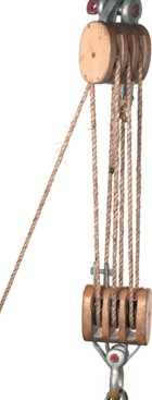
- Block and tackle
- Chain hoists
- Come-alongs
- Tirfor jacks
Block–and–Tackle
A block-and-tackle uses fibre ropes rather than wire rope. It is capable of increasing lifting capacity. This increase can be calculated by counting the number of ropes leaving the travelling block or by counting the number of sheaves (grooved wheels). For example, a with four sheaves, two on the fixed block and two on the movable block, can lift a 1000 kg load by exerting a pull of only 250 kg. This is important because the load being lifted may exceed the rope’s breaking strength.
A block-and-tackle has no braking device or safety system. It cannot support a load unless the line is anchored.
Snatch Blocks
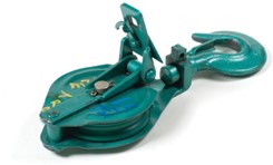
A snatch block is a pulley block with a side plate that swings open. Because the side plate opens, the cable does not need to be threaded through the block opening; instead the side plate is opened and the bight of the cable is placed over the pulley.
Chain Hoists
Chain hoists (also known as chain falls or endless chains) are dependable and economical devices for vertical lifting. Both manually operated and electrically powered models are available. They are designed to move loads either up and down or sideways, but never both at the same time.
Chain hoists are most often used for vertical lifts but can also be used for horizontal pulls. They are hand-operated and available in a wide range of capacities, from 450 kg to 9000 kg ([latex]\frac{1}{2}[/latex] ton to 10 tons). The lifting capacity of a chain hoist must be clearly marked on the hoist, and must never be exceeded.
Movement is relatively slow, and the lifting distance is limited by the length of the lifting chain.

“Endless” Chains
An “endless” hand chain turns the drive pulley. The drive pulley is connected to the lifting chain through a series of reduction gears that multiply the amount of force the operator exerts on the hand chain. To lower a load, you simply pull the hand chain in the opposite direction. Endless-chain hoists have the advantage of holding the load without requiring a separate brake.
“Come-Along”
Come-alongs (also called pullers) are similar to chain hoists but are operated by a ratchet lever rather than an endless chain. They are more convenient for horizontal pulls than chain hoists because they are compact, although they usually have a smaller lifting capacity than chain hoists. Similar to chain hoists, the rated capacity for come-alongs must be clearly marked and must never be exceeded.
Come‑alongs are commonly used in repair shops to pull heavy parts into position before welding or bolting. Inspection procedures include checking the lifting medium (chain or wire rope). Safety requirements for wire rope, chain, and other attaching devices are equivalent.
Never substitute regular chain for the original lifting chain supplied with the come-along. Do not use any extensions on the handle to increase leverage.

Tirfor Jacks
Tirfor jacks (see Figure 42) are hand-operated lifting or pulling devices with an unlimited rope travel distance. They work by applying a direct pull on a wire rope that typically has a hook attached to one end and a plain end on the other (the plain end is fed through the Tirfor jack first). The pulling force is applied through two pairs of self-energizing smooth jaws that grip the rope in proportion to the load. The initial pressure that causes the jaws to grip the rope and starts the self-energizing action is provided by springs that exert a pressure of about 800 kPa (120 psi).
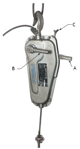
Two levers (A and B) activate the jaws to move the rope forward or backward, depending on which lever is used. The release lever (C) must never be left in the released position. A removable pipe handle is used to operate the levers. The jack may be attached directly to the load or anchored near the ground.
Always position the jack so that you will not be harmed or injured if the load drops.
Tirfor jacks are available in three capacities: 750 kg (1600 lb.), 1600 kg (3500 lb.) and 3200 kg (7000 lb.). All Tirfor jacks models include overload protection consisting of a shear pin in the lifting-lever connection (Figure 42B), which breaks if the load weight exceeds the rated capacity, preventing further movement of the load.
Never replace the specific wire rope used with the Tirfor jack with another piece of wire rope unless the replacement rope meets the exact same specifications as the original.
Electric Hoists
Electric hoists are much faster and more productive than manual hoists, although they are often more expensive. They usually have a push-button control suspended from a chain or wire rope. Both manual and electric hoists may be stationary or movable. Movable types are used on overhead runways, gantry cranes, jib cranes, and overhead travelling cranes.
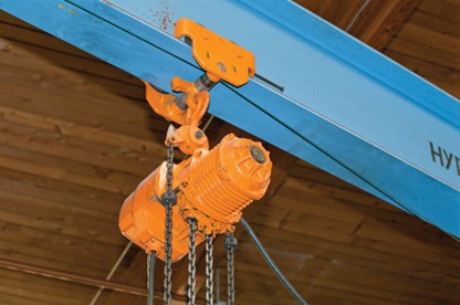
Some hoists are manually pulled along the overhead runway or boom, while others are motor driven. Hoists are manufactured in many capacities.
Workplace regulations typically require all trolleys to be equipped with drop stops, which are automatic brakes that prevent the load from falling.
Floor Hoists
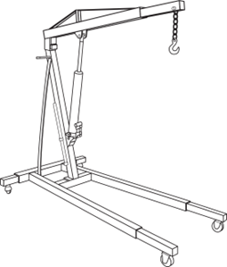
A typical hydraulic floor hoist or floor crane is shown in Figure 44. The lifting reach can be adjusted by moving the boom in or out. However, as the boom extends, the lifting capacity decreases. The rated lifting capacity of these hoists is based on lifts with the boom fully extended. Floor hoists are available in various sizes and may be manually, hydraulically, or electrically powered.
Superstructures for Hoists
Hoists are generally suspended from an overhead support (a superstructure) that may be stationary and provide for only vertical lifting or may allow the load to be moved from one area to another horizontally. These support structures must have a safe lifting capacity greater than the capacity of the hoist, and the safe capacity must be clearly marked.
All superstructures and supports must be certified by the engineer or manufacturer for lifting capacity.
Gantry Cranes
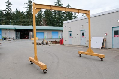
One of the most basic support structures that can also provide mobility is the gantry crane. With this superstructure, the load can be lifted and the entire crane assembly and the load can be moved to another area.
Overhead Runways
Runways usually consist of H-type or I-type structural steel beams fastened to heavier cross beams on the ceiling or mounted on floor supports. The hoist is attached to rollers or trolleys that run along the bottom flange of the beam.
Runways are used extensively in shops to move materials. They often extend from outdoor loading, unloading, and storage areas right into the shop. Switches, loops, and drop arms can be installed to move materials to strategic locations.
Jib Crane
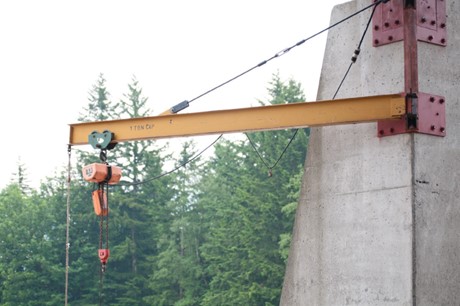
Another type of support structure is the jib crane, which features a boom attached to a vertical member that rotates. Jib cranes may be wall-mounted or pedestal-mounted. Entire jib-crane assemblies can also be mounted on rails to move materials between areas of a shop.
Overhead Travelling Cranes
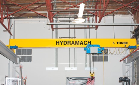
Overhead travelling cranes (also called bridge or gantry cranes) may be top-running or under-running, depending on where the hoist assembly is mounted. Top-running cranes generally have greater load-carrying capacity. The trolleys on which the hoist assembly moves is mounted on top of bogeys (end-trucks) that move along parallel runways. Under-running travelling cranes are used for lighter loads, usually not more than 907 kg (2000 lb.). In these systems, the hoist‑carrying bridge or beam is mounted on trolleys.
Mobile Lifting Equipment
Mobile lifting equipment used in the piping trades includes cranes, boom trucks, loaders, Tirfor jacks, and “tuggers.”
Tuggers
Tugger is a broad term that refers to an electric or hydraulic drum winch. Some electric winches can be bolted to a wall or floor and used with a snatch block (pulley block) to lift pipes into place in a mechanical room.
Mobile Hoists
Boom Trucks
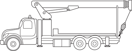
Boom trucks are mobile hoisting units with three features:
- A hydraulic crane mounted on the truck chassis for lifting heavy loads.
- A flatbed for transporting equipment and materials.
- (Often) a personnel hoist or fibreglass basket that allows workers to reach elevated work areas.
Boom trucks are often equipped with outriggers for stability. Boom styles can vary from straight telescopic to articulating, and capacities generally range from 3 to 75 tons, with reaches of 12 to 21 metres.
Boom truck operators require proper training and certification.
Part 14: Cranes and Hoists of the OHS Regulation requires annual inspections of boom trucks and requires that they not be used unless a professional engineer certifies that the structural, mechanical, and control components of the truck are safe for use.

Forklifts
No person may operate a forklift without training. All training must typically be provided in accordance with the requirements of CSA Standard B335-94, Industrial Lift Truck Training.
One of the most common types of materials-handling equipment is the motorized forklift, used for lifting and transporting materials that can be stacked or placed on pallets.
The main identifying features of the forklift are the two horizontal arms (or forks) that extend from the vertical mast (Figure 49). The mast can tilt forward between 10° and 25°.
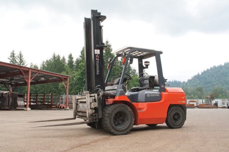
The forklift’s load-lifting capacity depends on the spacing of the forks, the height and tilt of the mast, and the floor or ground surface conditions. Lifting capacities range from 907.2 kg to 31 752 kg (2000 lb. to 70 000 lb.). Forklifts may be powered by electricity or internal combustion engines.
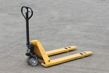
Manual forklifts (also called pallet trucks or pallet jacks) are hand propelled units used to lift and move palleted loads on smooth floors.
They cannot be used to stack loads one on top of the other, as their maximum lift height is only 150–200 mm (6–8 in.) above the floor. They have small steel wheels under the forks and require smooth surfaces to travel on when loaded.
The pallet jack shown here uses a hydraulic jack that is operated by pumping the handle to raise the forks. Travel is achieved by pushing or pulling. Loads can be lowered gently to the floor by using a control lever on the handle.
Rollers
Rollers can be used to move heavy objects by hand. Commercially available rollers can support many tons and consist of a series of roller bearings that rotate around a central core. These rollers are often used by house movers and modular-building installers.
On construction sites, large heavy items such as full skids of pipe often need to be moved. These heavy loads can be moved using a jack and several pieces of steel pipe. The pipe should be approximately 50–75 mm (2–3 in.) in diameter, and the jack must be strong enough to safely lift one end of the load. A minimum of three pipes is required, and sometimes two jacks.
To Move the Load
- Jack up one end of the load enough to place two of the pipes under the load.
- Position the jack at the end of the load closest to the load’s final location.
- Place one pipe past the midpoint of the load and the second pipe near the jack.
- Lower the load onto the pipes.
- Push the load towards its final destination.
- As the load moves, place the third pipe in front of the load and allow the load to roll onto it.
- As the load rolls off the last pipe, move that pipe to the front and continue the process.
This method only works if the ground is firm enough to prevent the rollers from sinking and the surface is somewhat free of small debris.
Safety Considerations
- Never allow the rollers to protrude excessively from the edge of the load.
- Keep your hands and feet clear of the rollers and the load. Watch for pinch points.
- Stay clear of the load at all times.
- Practice with light loads before applying these procedures to heavy loads.
 Self-Test B-4.2: Describe Hoisting, Lifting and Rigging Equipment
Complete Self-Test 4.2 and check your answers.
If you are using a printed copy, please find Self-Test A-4.2 and Answer Key in the Appendix at the end. If you prefer, you can scan the QR code with your digital device to go directly to the interactive Self-Test.

References
BC Industry Training Authority. (2019). Piping trades apprenticeship program: Use Tools and Equipment—Level 1 harmonized [Binder]. Crown Publications, Queen’s Printer for British Columbia. https://www.crownpub.bc.ca/Product/Details/7960000261_S
Camosun College. (2019). Line C: Tools and Equipment—Competency C-2: Describe Common Power Tools and Their Uses (Rev. ed.) [Learning guide]. BCcampus. https://collection.bccampus.ca/textbook/zAYtfTec/
Camosun College. (2015). Trades Access Common Core Competency C-2: Describe Common Power Tools and Their Uses. Victoria, B.C.: Crown Publications. Download for free from the B.C. Open Textbook Collection (https://open.bccampus.ca/browse-ourcollection/find-open-textbooks/).
CSA Group. (n.d.). CSA store product page (Product No. 2410931). https://www.csagroup.org/store/product/2410931
WorkSafeBC. (n.d.). Occupational health and safety regulation. https://www.worksafebc.com/en/law-policy/occupational-health-safety/searchable-ohs-regulation/ohs-regulation/
WorkSafeBC. (n.d.). Occupational health and safety regulation: Part 14—Cranes and hoists. https://www.worksafebc.com/en/law-policy/occupational-health-safety/searchable-ohs-regulation/ohs-regulation/part-14-cranes-and-hoists
WorkSafeBC. (n.d.). Occupational health and safety regulation: Part 15—Rigging. https://www.worksafebc.com/en/law-policy/occupational-health-safety/searchable-ohs-regulation/ohs-regulation/part-15-rigging
Media Attributions
All figures are sourced from Industry Training Authority (2019) and/or Camosun College (2019) and are used under the Creative Commons Attribution 4.0 (CC BY 4.0) licence unless otherwise noted. Images copyrighted by the BC Industry Training Authority are licensed under a Creative Commons Attribution-NonCommercial-ShareAlike 4.0 (CC BY-NC-SA 4.0) licence.
- Figure 50 Boom truck Grove Street downtown Brattleboro VT April 2024, by Artaxerxes on Wikimedia Commons is used under a CC BY 4.0 license.
A metal device used to adjust the tension or length of ropes, cables, or slings. It has a threaded body with two threaded ends that can be tightened or loosened by rotating the central frame. (Section B-4.5)
A bolt with a looped head used as a strong attachment point for lifting loads. (Section B-4.2)
A U-shaped metal connector with a removable pin used to attach slings, ropes, or chains to a load or lifting device during rigging and hoisting operations. (Section B-4.2)
A dangerous rigging condition where a load is applied to the sides of a shackle instead of to the pin and curved body. This can weaken the shackle and may cause it to bend or fail during lifting. (Section B-4.2)
A method of attaching a sling to a load by passing one end of the sling around the load and then hooking it back onto itself. This creates a tightening grip that helps hold the load securely during lifting. (Section B-4.2)
A metal fastener used to secure the end of a wire rope back onto itself to form a loop. It consists of a U-bolt, saddle, and nuts that clamp the rope together. (Section B-4.2)
A type of cable clip that has two saddles instead of a U-bolt. It grips both sides of the wire rope evenly and is often used for stronger or more secure wire rope connections. (Section B-4.2)
A metal fitting placed inside the eye (loop) of a wire rope or fibre rope to protect it from wear and crushing. The thimble helps the rope keep its shape and prevents damage when the rope is attached to hooks, shackles, or other rigging hardware. (Section B-4.4)
The forward-leaning edge of a saw tooth that helps pull the blade into the material during cutting. (Section B-2.1)
(shake-out hook): A long, narrow hook used in rigging to pick up or separate steel plates, beams, or other stacked materials. Its thin shape allows it to slide between tightly stacked pieces so they can be lifted safely. (Section B-4.2)
A spring-loaded latch attached to a hook that closes the opening of the hook to prevent a sling, rope, or chain from accidentally slipping off during lifting. (Section B-4.2)
The curved bottom part of a lifting hook where the load should sit. The saddle is the strongest part of the hook and is designed to safely support the weight. (Section B-4.2)
A rotating connector used in lifting and rigging that allows a hook, chain, or sling to turn freely. This helps prevent twisting of the lifting equipment while a load is being lifted or moved. (Section B-4.2)
A type of choker hook that can move along a sling and be positioned where needed. It allows the sling to wrap around a load and tighten to form a choker hitch, helping hold the load securely during lifting. (Section B-4.2)
Protective padding placed between a sling and the sharp edges or corners of a load. Softeners help prevent damage to the sling and reduce wear or cutting while lifting. (Section B-4.2)
A large metal link used to connect multiple slings or chains to a lifting hook. (Section B-4.2)
safe working load (SWL) – The maximum weight that lifting equipment can safely lift without breaking or failing. (Section B-4.2)
A rigging method that uses two or more sling legs attached to a single lifting hook to lift a load from multiple points, helping distribute the weight and keep the load balanced during lifting. (Section B-4.2)
A lifting method where a sling is passed under or through a load and both ends of the sling are attached to the lifting hook, forming a “basket” that supports the load from underneath. (Section B-4.2)
A lifting method that uses two basket hitches placed under a load to support it at two separate points. This arrangement helps distribute the weight evenly and keeps the load stable during lifting. (Section B-4.2)
A type of sling made as a continuous loop of rope, wire rope, or webbing with no fixed ends. Endless slings can be wrapped around loads in different ways for lifting and are often used because they distribute weight evenly and are flexible to position. (Section B-4.2)
A lifting bar that helps spread the weight of a load evenly between multiple slings or lifting lines. (Section B-4.2)
A lifting system made of two or more pulleys (called blocks) with a rope or cable threaded between them. It allows a heavy load to be lifted using less force by spreading the weight across multiple rope sections. (Section B-4.2)
A grooved shell or pulley used to redirect force upon a hoist line. (Section B-4.6)
A pulley with a side plate that opens so a rope or cable can be placed over the wheel without threading the entire line through it. Snatch blocks are commonly used to change the direction of a pull or to increase lifting or pulling power. (Section B-4.2)
A lifting device that uses a chain and gears to raise or lower heavy loads. It is usually operated by pulling a hand chain, which turns gears that lift the load using a second chain attached to the hook. (Section B-4.2)
A continuous loop of chain used to operate a chain hoist. Pulling the chain in one direction raises the load, while pulling it in the opposite direction lowers it. (Section B-4.2)
A hand-operated device that uses a ratchet and lever to pull, lift, or tighten heavy loads. It works by tightening a chain or wire rope in small steps, allowing workers to move or position equipment safely. (Section B-4.2)
A hand-operated lifting or pulling device that uses a wire rope and gripping jaws to move heavy loads. By operating a lever, the device pulls the rope through the mechanism to lift, lower, or pull materials with controlled force. (Section B-4.2)
Safety devices installed on lifting equipment, such as trolleys or hoists, that prevent the load or trolley from accidentally falling or running off the end of a beam or track. (Section B-4.2)
The supporting framework or structure above the base of lifting equipment that holds and supports hoists, cranes, or other lifting devices during operation. (Section B-4.2)
A type of crane that has a horizontal beam supported by two legs that move on wheels or rails. A hoist travels along the beam to lift and move heavy loads in workshops, warehouses, or construction sites. (Section B-4.2)
A type of crane that has a horizontal arm (called a jib or boom) attached to a vertical support. The arm can rotate, allowing loads to be lifted and moved within a circular area. (Section B-4.2)
A crane that moves along overhead beams or rails and uses a hoist to lift and move heavy loads across a workspace. (Section-B-4.2)
A type of overhead travelling crane where the crane bridge runs on rails mounted on top of runway beams, allowing it to carry heavier loads. (Section B-4.2)
A type of overhead travelling crane where the crane bridge is suspended from the underside of runway beams, typically used for lighter loads. (Section B-4.2)
Wheeled assemblies located at each end of an overhead travelling crane bridge that allow the crane to move along the runway beams or rails. (Section B-4.2)
A powered winch, usually electric or hydraulic, that pulls or lifts heavy loads using a drum and cable or rope. Tuggers are commonly used to move pipes, equipment, or materials into position. (Section B-4.2)
A mechanical device used to pull or lift loads using a rotating drum and cable. (Section B-4.2)
A truck equipped with a hydraulic crane mounted on its chassis and a telescoping or articulating boom used to lift, move, and position heavy loads at construction or work sites. (Section B-4.2)
A hand-operated device used to lift and move loads placed on pallets. It uses a hydraulic mechanism and small wheels to raise the pallet slightly off the floor so it can be pushed or pulled across smooth surfaces. (Section B-4.2)