B-5.1 Describe Oxy-Acetylene Equipment
Fuel Gases
Fuel gases are extensively used in the pipe trades for cutting, welding, brazing, and soldering metals, so it is important that you know the properties of these gases. It is also important that you learn how to handle, store and transport the various components of a welding outfit safely and correctly.
Oxy-Fuel Gases
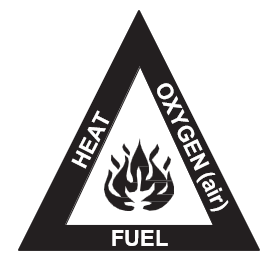
The process of gas cutting, brazing, or soldering requires two gases and a source of ignition:
- Oxygen
- A fuel gas such as acetylene, MAPP, natural gas, propane
Oxygen
Oxygen is the element in our atmosphere that supports combustion (the process of burning). Second only to nitrogen in its volume, oxygen is the other major component of the air we breathe. It is a colourless, odourless, tasteless gas at ordinary temperatures. By itself, it is slightly heavier than air. One of the hazards of oxygen is that it accelerates combustion rapidly and raises the combustion temperature of fuel gases, which can cause hazards if the oxygen content is above standard atmospheric percentage (20.8%). Oxygen must be considered potentially dangerous because it combines readily, and in some cases explosively, with many substances.
Under normal conditions, the heavy nitrogen content in air tends to retard combustion and reduce the flame temperature. Combustion with pure oxygen is much faster than combustion in air (which is a mixture of gases), and this increases the flame temperature. In general, materials that burn in air burn much more rapidly in pure oxygen. It is also true that some materials that are not considered combustible in air will burn readily in oxygen-enriched atmospheres. The acceleration of combustion is called the oxidizing effect. Under WHMIS provisions, oxygen must be appropriately labelled, stored, and handled using specific safe work procedures.
Rubber and Oxygen
Rubber will burn in air. The flame is dull red, smoky, and gives off a heavy odour. When rubber burns in oxygen, it burns rapidly, with a white flame, high flame temperature, almost no smoke, and little odour.
The hoses of an oxyacetylene outfit are made from rubber and cotton and you must exercise caution to keep them from being burned, cut, or ruptured. If either hose on the equipment catches fire while under pressure, the fire cannot be extinguished using a fire extinguisher alone. This is because oxygen is being fed to the flames from inside the hose. A fire extinguisher works on the principle of excluding oxygen from the air and thereby smothering the flame; it can only be used after you stop the flow of oxygen and acetylene. You must turn off the supply of oxygen and fuel gas before attempting to put out the fire using a smothering-type extinguisher. The fire will continue to burn as long as fuel and oxygen is supplied to it from the hoses because the rupture in the hose acts as a torch opening.
Oil or Grease and Oxygen
At normal temperatures, oil or grease is not considered to be highly flammable, but if either one is brought into contact with pure oxygen under slight pressure, a violent explosion can occur.
Keep oxygen equipment away from oil, grease, oil-based cleaning fluids, and gasoline. Never use oil to lubricate regulators or any part of the torch.
Oxygen + Oil = Potential Explosion
Steel and Oxygen
Although steel is not normally considered to be combustible, when it is heated to a red heat and brought into contact with oxygen (as it is during the cutting process), it burns quite rapidly and reduces the reacted metal to iron oxides. An oxyacetylene cutting attachment allows this burning process to be controlled while cutting steel plate. Steel will also combine with oxygen and moisture, causing the steel to oxidize slowly (rust).
Oxygen must always be considered a potential danger because it speeds up the combustion of known flammable materials and combines readily, and often explosively, with materials not generally considered combustible.
Acetylene
Acetylene is a compound formed by uniting two atoms of carbon (C2) with two atoms of hydrogen (H2) to form a molecule of acetylene (C2H2). Like oxygen, acetylene gas is colourless, but it has a pungent, garlic-like odour. Only 1% of acetylene present in the air is quite noticeable to the average person’s sense of smell, making it easy to detect. Acetylene can form combustible mixtures in almost any concentration. It has explosive limits (allowable concentrations that will support combustion) between 2.5% and 81%, giving it one of the widest available ranges of flammability for any fuel gas.
Acetylene gas generates high heat when burned. When it is proportionately mixed with oxygen, as it is in the oxyacetylene gas welding process, the resulting flame can reach 3300°C (6000°F). This is the highest flame temperature derived from the combustion of any two gases, making the combination of oxygen and acetylene useful for gas welding, metal cutting, and brazing.

Acetylene gas is flammable and highly explosive.
It is important to treat all mixtures of oxygen and acetylene as potentially explosive. Acetylene can quite easily be detected. The moment you smell it, extinguish all open flames immediately and ventilate the room even before turning on a light switch. Then test for leaks in the lines by brushing soapy water on suspected joints or areas. Watch for bubbles. Never test for leaks near an open flame.
Acetylene is an unstable compound. The term “unstable” means that the material is likely to break down (decompose) or undergo a physical change without much provocation or cause. The point at which this happens is said to be its critical point.
The critical point of free acetylene is 28 psi (193 kPa) at a temperature of 70 °F (21 °C), which is the calibration temperature for most acetylene gauges. If this pressure is reached, acetylene breaks down into carbon and hydrogen, and an explosion results. If the temperature is increased, the pressure at which acetylene becomes critical is lowered. To allow for any temperature fluctuations in the work area, acetylene should not be stored or used at pressures over 15 psi (103 kPa).
When acetylene is put in a gas cylinder, the cylinder is packed with a porous filler such as asbestos, charcoal, or balsa wood and then filled with liquid acetone into which the acetylene is dissolved. This keeps the acetylene from reaching its critical point by not allowing it to be free. Acetylene can then be stored in cylinders at pressures of about 250 psi (1.7 MPa).
Never use copper or red brass for fittings, tubing, etc. with acetylene systems. Acetylene gas reacts with copper to form acetylide, a residue that is even more unstable than acetylene. The slightest shock may cause an explosion and fire. Use only fittings of yellow brass, iron, or steel with acetylene.
Other Fuel Gases
For economic reasons, fuel gases other than acetylene are used for preheating in flame cutting. Three of the more common gases are:
- MAPP gasTM (methylacetylene-propadiene)
- Natural gas (primarily methane)
- Propane gas
These gases are used for flame cutting operations, and in some cases, preferred over acetylene. While acetylene and oxygen produce the highest flame temperature, which permits fast starts when cutting, this combination tends to leave slag at the bottom of the cut. The other fuel gases, although having lower flame temperatures and therefore slower starts, will produce cleaner cuts with little or no slag clinging to the bottom of the cut.
MAPP Gas
MAPP gas is a trademarked name belonging to Dow Chemical, for a fuel gas based on a stabilized mixture of methyl acetylene and propadiene. The name comes from the original chemical composition: methylacetylene-propadiene propane.
MAPP gas is shipped in low-pressure cylinders in liquid form, so it must be used in an upright position. Although it provides less heat than acetylene, it is safer to use and may be safely compressed.
One MAPP cylinder is roughly equal to five acetylene cylinders in terms of equivalent cutting and welding capacity. The flame temperature, 2900°C (5300°F), is lower than acetylene, but the gas is stable and relatively inexpensive when compared to the cost of acetylene.
Natural Gas
Natural gas is preferred in areas where it can be piped in, eliminating the handling of fuel gas cylinders. It is not shipped in a liquid form. The main constituent of natural gas is methane. The flame temperature reaches 1980°C (3600°F), lower than acetylene or MAPP gas. Natural gas requires two volumes of oxygen to one volume of fuel to burn completely. Because of its lower flame temperatures and reduced heating efficiency, either longer preheating or slower cutting speeds are required.
Natural gas is inexpensive compared to acetylene.
Propane Gas
Propane gas is supplied in liquid form in low-pressure cylinders for easy, safe handling. It is widely used because of its ability to produce clean cuts at a relatively low cost. Propane has a high heat value, but requires 4[latex]\frac{1}{2}[/latex] volumes of oxygen to one volume of fuel to produce a neutral flame. The flame temperature is 1980°C (3600°F).
Specially designed cutting tips and, in some cases, mixing chambers are necessary with the liquid fuels (MAPP and propane) as the amount of oxygen required for burning it is considerably higher than for acetylene. Of the four fuel gases mentioned, acetylene and propane are the two most common. Table 1 illustrates the key characteristics of these two gases.
|
Acetylene |
Propane |
|
Hydrocarbon C2H2 |
Hydrocarbon C3H8 |
|
Burning rate through tip is 100 m/s (300 ft./s) using approximately a 1:1 mixture with oxygen. |
Burning rate through tip is 18 m/s (60 ft./s) using approximately a 1:4 mixture with oxygen. |
|
Flame temperature approximately 3000°C (6000°F). |
Flame temperature is approximately 2540°C (4600°F). |
|
Principal uses are flame cutting, heating, fusion welding, braze welding and hard- facing. |
Principal uses are flame cutting and heating. |
|
Advantages are high flame temperature, reduced preheat time and the capacity to perform a wide variety of tasks. Disadvantage is high cost. |
Advantage is low cost. Disadvantage is restricted use due to lower flame temperature. |
Gas Cylinders
Oxygen cylinders are forged in one piece from high-grade steel plugs for strength. At the slightest sign of damage, the cylinders are withdrawn from service. Cylinders are not generally sold, but remain the property of the supplier, and are loaned out for a certain period of time. Only full cylinders of gas are distributed. The returned cylinders are drained of any remaining gas in case it is contaminated, and then refilled. Cylinders must be labelled according to WHMIS regulations and the Workers’ Compensation Board regulations.
Oxygen cylinders are made in various sizes, ranging from 0.5 m3 to 7 m3 (20 ft3 to 244 ft3) capacity (this may vary slightly with each manufacturer). The oxygen is compressed to 2200 psi (15 MPa) at 21 °C (70 °F). Figure 2 shows a 7 m3 (244 ft3) cylinder.
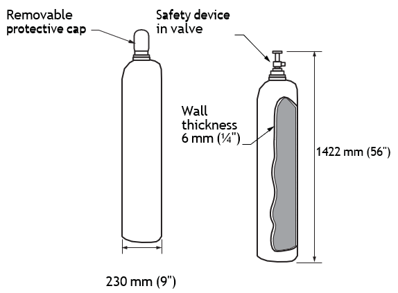
The cylinder valve is protected by a screw-on protective cap. The cylinders and protective caps are usually black, although green and other colours are used occasionally. The caps have right-hand threads (like all oxygen fittings) and come in various sizes to match the cylinders.
Table 2 provides an indication of how temperature change significantly alters the pressure of a full oxygen cylinder:
|
Temperature |
Pressure (approximate) |
||
|
Celsius |
Fahrenheit |
MPa |
PSI |
|
49 |
120 |
17.3 |
2500 |
|
38 |
100 |
16.4 |
2380 |
|
27 |
80 |
15.5 |
2246 |
|
21 |
70 |
15.2 |
2200 |
|
16 |
60 |
14.8 |
2140 |
|
10 |
50 |
14.3 |
2080 |
|
4 |
40 |
13.9 |
2020 |
|
–1 |
30 |
13.5 |
1960 |
|
–7 |
20 |
13.1 |
1900 |
|
–12 |
10 |
12.7 |
1840 |
|
–18 |
0 |
12.3 |
1780 |
|
–23 |
–10 |
11.9 |
1720 |
|
–29 |
–20 |
11.5 |
1660 |
It is important to monitor the amount of oxygen in the cylinder. When the flame is no longer consistent and the working pressure cannot be maintained, remove the cylinder from service. This will prevent poor welds and decrease the possibility of fire or explosion.
Oxygen Cylinder Valves
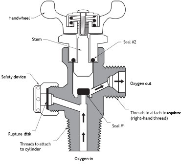
The oxygen cylinder valve is designed to operate at high pressures. The double-seal construction prevents leakage of oxygen around the stem when the valve is completely opened. When the valve handle is turned clockwise (closing it), pressure is forced down on seal #1, which shuts off the oxygen supply to the regulator. When the valve is turned counter-clockwise (opening it), pressure is released from seal #1, allowing oxygen to flow into the regulator. The part above seal #1 then threads upward, forcing pressure onto seal #2. This cuts off any oxygen travelling up and around the stem. The outlet fitting for the regulator has a standard external thread to which all standard oxygen pressure regulators may be attached.
Before attaching the regulator, the valve should be “cracked” (briefly opened and re-closed) to remove any dirt that may be lodged in the passage to the regulator.
Never attempt to repair a damaged valve. Tag the cylinder to indicate the fault, move it to an open area, and immediately notify the supplier.
Cylinder Safety Devices
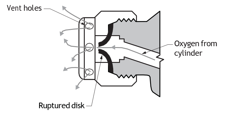
The safety device for the oxygen cylinder is located in the valve. It consists of a pressure or rupture disc, which will burst and release cylinder oxygen into the air when excessive pressure build-up occurs, such as from an increase in temperature.
Acetylene Cylinders
The instability and explosiveness of acetylene requires that the gas be handled with extreme caution at all times, and special considerations are made in construction of the acetylene cylinder.
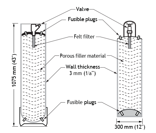
The acetylene cylinder is a strong, welded-steel container completely filled with a porous material called agamassan (a porous material such as asbestos, charcoal or diatomaceous earth). This filler material is saturated with acetone, a straw-coloured, stable liquid that is flammable, volatile and strong smelling. Acetone has the ability to absorb acetylene gas and is used in the cylinders to make them safe at high pressures by stabilizing the acetylene. One volume of acetone will absorb 20 volumes of acetylene gas at atmospheric pressure. This ratio increases as pressure is increased.
Because the acetone is in liquid form, acetylene cylinders must be used in an upright position. Otherwise, the acetone may flow into and contaminate the regulator, hose, torch, and flame.
Free acetylene gas is dangerous when stored at pressures above 15 psi (103 kPa), but when porous material and acetone are used, the manufacturer is able to charge the cylinders to an average pressure of approximately 250 psi (1.7 MPa) to 350 psi (2.4 MPa).
It is important to monitor the amount of acetylene in a cylinder. When the flame is inconsistent and the working pressure cannot be maintained, remove the cylinder from service (to prevent acetone from being drawn off into the lines).
Acetylene Cylinder Valves
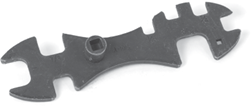
Unlike the special double-seal design of the high-pressure oxygen cylinder valve, the acetylene cylinder valve has a simple construction to accommodate the relatively low pressure. The valve is opened with a removable wrench or hand wheel. It should be slowly opened [latex]\frac{1}{4}[/latex] to [latex]\frac{1}{2}[/latex] turn. Leave the handle in place in case it must be shut off quickly. When the handle is turned counter-clock-wise (opening it), pressure is released from the seal, allowing acetylene to flow to the regulator.
Cylinder Safety Devices
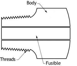
The safety device for the acetylene cylinder consists of fusible (heat-activated) plugs threaded into the top and bottom of the cylinder. Excessive heat causes these alloy plugs to melt, which in turn releases the cylinder contents to avoid an unsafe pressure rise. The average range of melting temperatures for these plugs is 104 °C to 115 °C (220 °F to 240 °F).
Liquid Fuel Cylinders
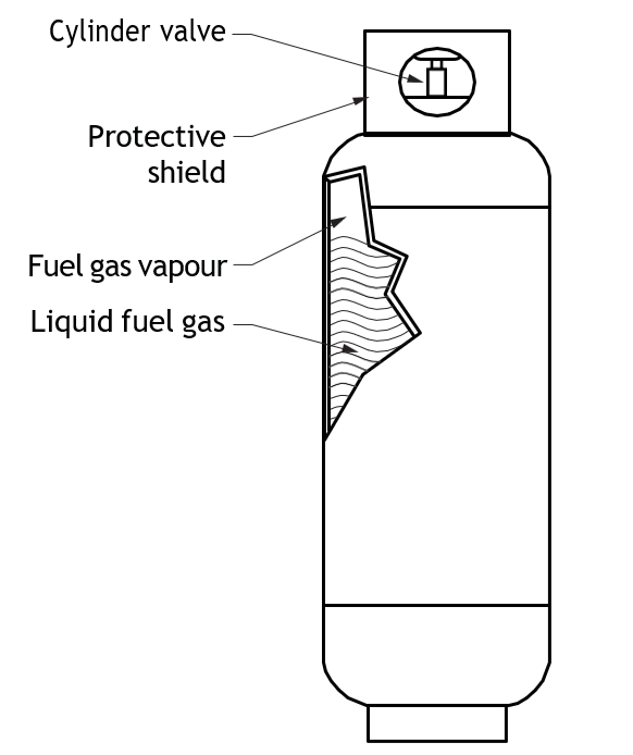
Fuels such as propane and MAPP gas are liquids when stored in cylinders. When the cylinders are shipped full, there is still a space above the liquid for gas (vapour) to occupy. Gas escapes when the cylinder valve is opened, reducing the pressure on top of the liquid. This allows the liquid to “boil off” (evaporate) more gas.
Since the cylinder contains a liquid, it must be operated in an upright (valve up) position to allow only the vapour to be withdrawn. These liquid fuel cylinders contain a greater yield of gas than an acetylene cylinder.
There are also cylinders designed to operate in a horizontal position, such as those used for RVs and forklifts. When intended for this purpose, they are marked as such and must be correctly positioned to function properly.
The flammable and explosive properties of the gases used in gas cutting, brazing and soldering make safety procedures essential at all times.
Storage
When storing cylinders outdoors, provision should be made for suitable cover from the weather. Full cylinders should be stored separately from empty cylinders; each type of gas should also have its separate storage location.
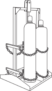
Cylinders should be stored where they will not be knocked over or damaged by falling objects, passing vehicles, or people. They should not come in contact with salt, corrosive chemicals or fumes. Cylinders (full or empty) should always be secured to a stationary object such as a wall to keep them from falling over.
- Cylinders should not be stored near radiators, stoves, or any other source of heat.
- All storage rooms should be well-ventilated.
- All cylinders should be used and stored in an upright position.
- Once a cylinder is empty, it is to be stored in the appropriate location and marked “MT.”
Manifold Systems
In special circumstances, large volumes of acetylene gas may be required to perform a particular job and a single cylinder may not provide enough acetylene at the rate required. When the maximum rate of removal (the draw limit) is exceeded, liquid acetone will be drawn from the cylinder. To prevent exceeding the draw limit, a series of acetylene cylinders are connected with a manifold. Manifolds are specially designed to connect a number of cylinders together so that the draw limit is increased. The manifold line is filled with stainless steel rod, steel shot, or silica sand to prevent the acetylene from reaching the critical point. The pressure is the same in the manifold as in the cylinders. These systems should be connected and used only by experienced and authorized persons.
Handling
Cylinders must always be handled very carefully. Never drop cylinders or allow them to bump together—they could tip over and explode. When cylinders are being transported, they must be fastened securely.
When your work is finished, close cylinder valves and put protective valve caps on before moving or storing the cylinders. Special cylinder carts should be used for moving cylinders.
Cylinders should be used in the order received from the supplier; when empty, their valves should be closed and the cylinders marked “MT.”
Keep cylinders away from electrical wires. Keep oxygen and acetylene cylinders as far away as possible from any area where sparks or flames from welding or cutting work could come in contact with them. Never weld directly over cylinders. If a cylinder valve is clogged with ice or snow, never use a flame or boiling water to loosen it. Use warm water.
To prevent a serious explosive reaction, keep oily and greasy substances away from oxygen cylinders, valves, hoses, fittings, and attachments. Never use oil or grease to lubricate regulators, torches, cylinder valves, or other oxy-fuel gas equipment.
Leaky acetylene cylinders should not be used. When leaks are present, the cylinder should be moved to an area where good ventilation exists. Warning signs should be displayed to caution people that smoking or using other sources of ignition are not allowed in the area.
The fusible safety plugs on acetylene cylinders should not be tampered with.
Never use a sling, choker, or hook when moving or hoisting cylinders with a crane, derrick, or other lifting equipment. A suitable cradle or box that has been certified and rigged by qualified personnel is the only acceptable method.
Regulators
Oxygen and fuel gases are stored in cylinders at higher pressures than what is required to perform a cutting, brazing, or welding task safely and efficiently. Because of this difference between the stored pressure in the cylinders and the working pressure required to perform welding or cutting operations, it is necessary to install a device on the cylinder that regulates or allows only the amount of pressure needed for a safe and effective operation.
A regulator must not be used for any type of service other than for which it was designed. Repairs to faulty regulators should only be performed by qualified service personnel.
When cylinders of gas come from the supplier, they do not have regulators attached. You must provide the right regulator for the type of fuel gas inside the cylinder.
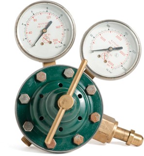
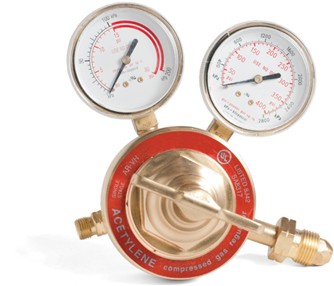
Most regulators have two calibrated gauges attached. Also included are the permanently attached hex nuts on the regulator cylinder connections. When connected to a cylinder, the gauge with the higher numerical calibrations indicates the pressure inside the cylinder. It is positioned on the same side as the cylinder connection. The gauge with the lower numerical calibrations indicates the working pressure you select. It is on the same side as the hose connection. Select a safe working pressure by turning the pressure adjusting screw on the regulator. Turning it clockwise increases the working pressure. Turning it counter-clockwise reduces the working pressure.
The oxygen regulator is always equipped with right-hand thread connections, and the acetylene regulator is always equipped with left-hand thread connections. This prevents installing the wrong regulators.
Oxygen Regulators
You can clearly identify an oxygen regulator by the following features:
- Right-hand thread connections
- Cylinder pressure gauge is calibrated from 0–4000 psi (most gauges are available in imperial calibrations only)
- Working pressure gauge is usually calibrated from 0–200 psi, but for heavy welding and cutting, it may read 400 or even 1000 psi
- The word “oxygen” should be printed on the regulator body and on one or both gauges
Note: Tag and remove any regulator that is found to be defective or damaged.
Acetylene Regulators
You can clearly identify the acetylene regulator by the following features:
- Left-hand thread connections (and grooved nuts)
- Cylinder pressure gauge is calibrated from 0–400 psi
- Working pressure gauge is calibrated from 0–30 psi
- Working pressure gauge has a red warning line from 15–30 psi
- The word “acetylene” should be printed on the regulator body and on one or both gauges
*Acetylene working pressure must be kept below 15 psi (103 kPa) to prevent the unstable gas from exploding.
All regulators are precision mechanisms. They should be treated with care and never dropped or misused. When they are removed, they should be stored in a box or suitable container to prevent damage. They should be cleaned with a dry, clean rag.

- If regulators are defective or damaged, they should be tagged and removed for service.
- Never use oil, grease, cleaning fluids, gasoline or other petroleum-based chemicals.
Oxy-Fuel Hoses and Fittings
Hoses that carry acetylene and oxygen are specifically designed for oxy-fuel applications. The hose consists of two or three layers of rubber, with a layer of strong fabric between each rubber layer for reinforcement.
The outside layer of rubber may be plain or ribbed.
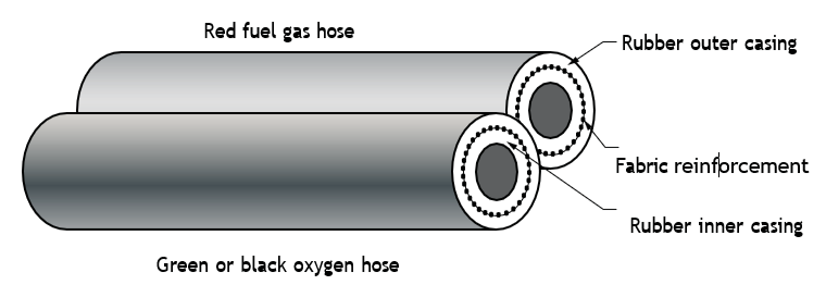
Most hose used for oxy-fuel application consists of two hoses that have outside layers of rubber fastened together to eliminate entanglements. Since single hose is more prone to kinking and wear, it usually has two layers of reinforcement to make it tougher.
To avoid serious explosions or fires, only use hose in good condition. Faulty or damaged hose should be repaired or replaced immediately with approved products.
Coil, tie, and store hose to avoid kinking. Never expose hose to oil, grease, cleaning solvents, gasoline, paint or contaminants of any kind, and keep hose away from direct sunlight.
Fittings
The same strict manufacturing and handling requirements that apply to oxy-fuel hose also apply to the fittings.
All fittings and connectors used in the hook-up of hose to the regulators and torch body are made of a brass alloy. This prevents sparks if the fittings should accidentally bang against another metal or material. Also, brass alloy fittings will not corrode or produce any dangerous by-products if oxy- fuel gases come in contact with them.
Hose fittings are also right-hand threaded for oxygen, and left-hand threaded for acetylene to prevent switching the hose and possibly causing an explosion. A distinct groove is cut around the outside of the hex nuts on acetylene fittings.
Damaged or faulty oxy-fuel fittings must be replaced immediately. Use only approved fittings.
Oxy-Fuel Torch Assembly and Reverse-Flow Check Valves
The torch assembly is the first point at which mixing of the oxy-fuel gases takes place. It is also the point at which the flow of gases can be adjusted for specific tasks.
Although torch assemblies vary in design, they all have similar characteristics. At one end, the torch handle has gas inlets where the oxygen and fuel gas hoses are attached. At the other end, the mixing barrel has a threaded outlet for the torch attachment. Separate valves control the amount of oxygen and fuel entering the torch handle.
Oxyacetylene flame is used to cut and fuse (weld) metal pieces, but each operation requires a different type of torch assembly. You must select and install the correct attachment to meet a specific job requirement.
Below is a combination torch. The cutting attachment and the welding tip shown can both be interchanged on a single torch handle. When used for cutting purposes, the oxygen valve on the torch handle is opened all the way, and the required amount of oxygen at the torch tip is adjusted by operating the preheat oxygen valve on the cutting attachment.
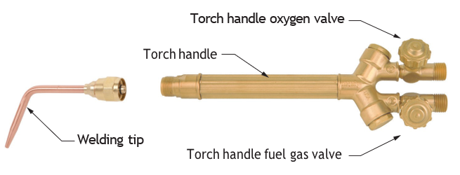
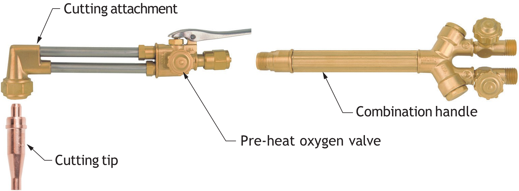
Both the oxygen and acetylene valves on the torch handle are used to adjust the amount of gas flow during welding or brazing processes.
When you purchase a combination torch assembly, it includes a cutting attachment, a torch handle and various sizes of cutting and welding tips. These components are specific to the manufacturer and cannot be used with other brands of torch assemblies.
When brazing with oxyacetylene, a combination torch may be fitted with a multi-port “rosebud” tip that is sometimes also used for preheating carbon steel pipe in fabrication work.

Torch Line Explosions
When acetylene and oxygen or acetylene and air mix, they form a highly explosive mixture. If this mixture ignites prior to exiting the torch head, it will cause a backfire or flashback explosion. This is a dangerous and uncontrolled explosion inside the torch equipment that can result in serious injury.
Backfire
During the welding or cutting process, the torch flame may burn back into the welding or cutting tip and make a “popping” sound. This is called a backfire and is usually the result of the gases pre-igniting inside the tip. The causes of backfire are:
- The obstruction of gas flow at the tip (carbon deposits, hot metal particles)
- A hot tip, from overuse or being too close to the work
- Working pressures too low
- A faulty connection between the torch handle and the welding or cutting attachment
Flashback
A flashback occurs when the backfire goes beyond the tip and through the hose to the regulator. The torch handle becomes hot, black smoke and sparks appear from the tip, a squealing or hissing noise is heard, and the fire may eventually burn through the hose. The result of a flashback, aside from fire damage, is a possible explosion.
The causes of a flashback are:
- Incorrect adjustment of torch valves
- Grossly unequal oxygen and acetylene working pressures
- A clogged tip along with excessive oxygen pressure
- Failure to purge the lines before igniting the torch
To help prevent backfire and flashback, make sure the valves on the torch and regulators are functioning properly. The tip should have a clear, undamaged orifice, and reverse flow check valves (RFCV) should be used to prevent reverse flow in the lines.
A backfire causes the flame outside the tip of the torch to go out and re-ignite instantaneously. If the trouble does not clear up immediately, carefully inspect the equipment, purge the lines, and light the torch.
In the case of a flashback, you must stop the flame IMMEDIATELY before an explosion happens. Assume the worst and shut down the torch valves and cylinder valves as soon as possible. A flashback indicates that something is wrong with the setup. Before you light the torch, check all equipment to see if it is damaged, purge each line separately, and check and adjust working pressures. If a flashback occurs again, remove the equipment from service and have it examined by qualified personnel.
The safe and efficient performance of the torch handle, cutting attachment, and welding tip is dependent on careful use and handling. They are precision tools that can easily be damaged from misuse. Never use a welding torch in place of a hammer or prying tool. When the handle and attachments are removed, they should be placed in a box and stored in a clean, dry area not exposed to oil, grease, solvents, or gasoline.
Reverse Flow Check Valves
The best way to prevent flashbacks and explosions is to keep the gases separated. You should regularly inspect the valves on the torch and cylinders, as well as the gauges on the regulators. Inspection cannot prevent gases flowing in reverse inside the torch or hose. A device called a reverse flow check valve or RFCV (Figure 16) is designed for this purpose (OH&SR Section 12.120). These check valves are compact and are installed between the torch and the hose, or between the hose and the regulators. A stainless steel compression spring holds the valve closed. When the operator opens the regulator and torch valves, the RFCV opens to permit normal gas flow, then snaps shut if the flow reverses.
Different check valves are used for oxygen and fuel gas and sometimes a check valve is built into a cutting attachment. It is important to note that all check valves are marked with an arrow to indicate the direction of gas flow.
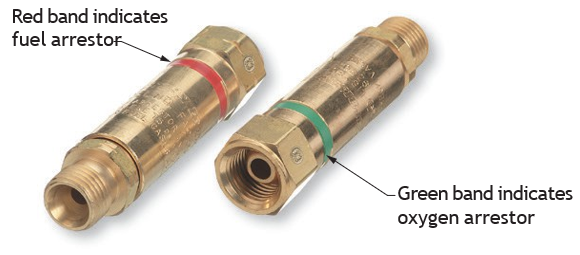
The WCB recommends that RFCVs be installed on both ends of the hose for safety. Since a torch is subjected to occasional banging or dropping, the RFCVs at that end of the hose may become faulty. Even with RFCVs at both ends of the hose, always check the operation of the valves at regular intervals.
A reverse flow check valve requires much more pressure to close the valve than to keep it open. A reverse flow check valve requires much more pressure to close the valve than to keep it open. For instance, 1.7 kPa (0.25 psi) pressure may open the valve to allow full flow of gases, but 4.3 kPa (1.6 psi) is needed to close the valve. This prevents the usual fluctuations in working pressure from repeatedly closing the valve. An increase in pressure occurs when heat is applied (as in a flashback), and the valve will close.
Reverse flow can be caused by:
- Using plugged or obstructed cutting, welding or brazing tips
- Bleeding the lines by turning off cylinder valves while torch valves are still open
- No pressure from either the oxygen or acetylene cylinders while the torch is in use (empty cylinders)
Flashback Arrestors
Flashback arrestors typically use a combination of methods to stop a flashback. They work just as effectively in any orientation, need very little maintenance, and are often small and light enough to be installed between the torch and hoses. They include:
- A flame trap to cool the flame front. They are designed to allow free flow of gas through them but they take the heat out of the flame front to get it below the ignition temperature of the burning gas mixture. The most common types are:
▸ Sintered metal or ceramic
▸ Layers of mesh
▸ Ceramic beads
- Temperature-triggered valves to stop the gas flow completely. Because it relies on extracting heat from the flashback to stop it continuing, most arrestors have a temperature- controlled valve that will cut off the gas flow when the unit reaches around 90 °C (195 °F), until either the unit cools (if the unit is automatic) or a reset button is pressed (if the unit is manual).
 Self-Test B-5.1: Describe Oxy-Acetylene Equipment
Complete Self-Test 5.1 and check your answers.
If you are using a printed copy, please find Self-Test A-5.1 and Answer Key in the Appendix at the end. If you prefer, you can scan the QR code with your digital device to go directly to the interactive Self-Test.

References
BC Industry Training Authority. (2019). Piping trades apprenticeship program: Use Tools and Equipment—Level 1 harmonized [Binder]. Crown Publications, Queen’s Printer for British Columbia. https://www.crownpub.bc.ca/Product/Details/7960000261_S
- Plumber: Competency B-5 Use Soldering and Brazing Equipment
- Plumber: Competency B-6 Use Oxy-Fuel Cutting Equipment
- Sprinkler Fitter: Competency B-4 Use Soldering and Brazing Equipment
- Steamfitter: Competency B-6 Use Soldering and Brazing Equipment
- Steamfitter: Competency B-7 Use Oxy-Fuel Equipment
Government of British Columbia. (n.d.). Occupational Health and Safety Regulation: Part 12 – Tools, machinery and equipment. BC Laws. https://www.bclaws.gov.bc.ca/civix/document/id/loo68/loo68/13_296_97-12
Health Canada. (2025, December 15). Workplace Hazardous Materials Information System (WHMIS). Government of Canada. https://www.canada.ca/en/health-canada/services/environmental-workplace-health/occupational-health-safety/workplace-hazardous-materials-information-system.html
Industry Training Authority. (2019). Piping trades apprenticeship program: Level 1—Competency B-4: Use soldering and brazing equipment (Sprinkler fitter). Crown Publications, Queen’s Printer for British Columbia.
Industry Training Authority. (2019). Piping trades apprenticeship program: Level 1—Competency B-5: Use cutting, brazing and soldering equipment (Plumber). Crown Publications, Queen’s Printer for British Columbia.
Industry Training Authority. (2019). Piping trades apprenticeship program: Level 1—Competency B-6: Use oxy-fuel cutting equipment (Plumber). Crown Publications, Queen’s Printer for British Columbia.
Industry Training Authority. (2019). Piping trades apprenticeship program: Level 1—Competency B-6: Use soldering and brazing equipment (Steamfitter). Crown Publications, Queen’s Printer for British Columbia.
Industry Training Authority. (2019). Piping trades apprenticeship program: Level 1—Competency B-7: Use oxy-fuel equipment (Steamfitter). Crown Publications, Queen’s Printer for British Columbia.
WorkSafeBC. (2025). Workers compensation act regulations. https://www.worksafebc.com/en/law-policy/workers-compensation-law/workers-compensation-act-regulations
Media Attributions
All figures are sourced from Industry Training Authority (2019) and/or Camosun College (2019) and are used under the Creative Commons Attribution 4.0 (CC BY 4.0) licence unless otherwise noted. Images copyrighted by the BC Industry Training Authority are licensed under a Creative Commons Attribution-NonCommercial-ShareAlike 4.0 (CC BY-NC-SA 4.0) licence.
The chemical process of burning that occurs when a fuel reacts with oxygen and releases heat and light. (Section B-5.1)
The ability of oxygen to make materials burn faster and hotter by helping combustion happen more easily. (Section B-5.1)
A mixture of oxygen and acetylene gases used in metalworking to produce a very high-temperature flame for welding, cutting, brazing, and heating metals. The oxyacetylene flame can reach temperatures of about 3300 °C (6000 °F), making it one of the hottest fuel-gas flames used in the pipe trades. (Section B-5.1)
A fuel gas made from carbon and hydrogen that burns very hot when mixed with oxygen and is commonly used for welding, brazing, and cutting metal. (Section B-5.1)
The range of concentrations of a flammable gas or vapour in air within which combustion or explosion can occur if an ignition source is present. Below the lower explosive limit (LEL) the mixture is too lean to ignite, and above the upper explosive limit (UEL) it is too rich to burn. (Section B-5.1)
The pressure or temperature at which acetylene becomes unstable and can break down suddenly, possibly causing an explosion. (Section B-5.1)
A straw-coloured, stable liquid that is flammable, volatile and strong smelling, placed inside acetylene cylinders; safely absorbs and stores acetylene gas under pressure. (Section B-5.1)
A highly unstable and explosive compound that can form when acetylene gas reacts with certain metals, particularly copper or copper alloys. Because acetylides can detonate from shock or heat, materials such as copper and red brass are not used in acetylene equipment. (Section B-5.1)
A hard residue left on a weld after metal is melted and fused together. (Section B-1.1)
A stabilized fuel gas mixture used in oxy-fuel cutting, heating, and brazing. It produces a high-temperature flame, though slightly lower than acetylene, and is valued for its stability, safety in storage, and suitability for metalworking applications. (Section B-5.1)
A combustible fossil fuel composed primarily of methane that is used as a fuel for heating, cutting, and other industrial processes. In oxy-fuel operations, natural gas can be used as a fuel gas with oxygen to produce a flame for heating or cutting metal, although its flame temperature is lower than that of acetylene. (Section B-5.1)
A flammable hydrocarbon fuel gas (C₃H₈) stored as a liquid in pressurized cylinders and widely used for heating and cutting operations. In oxy-fuel processes, propane is mixed with oxygen to produce a clean, controlled flame suitable for metal cutting and preheating, though its flame temperature is lower than that of oxyacetylene. (Section B-5.1)
A valve on top of an oxygen tank that opens and closes to control how much oxygen comes out. It keeps the gas safely inside the tank until you are ready to use it. (Section B-5.1)
A type of special porous, fire‑resistant material used to help keep equipment safe from heat and flames (e.g., asbestos, charcoal or diatomaceous earth); saturated with acetone. (Section B-5.1)
The highest amount of gas you can safely take out of a cylinder in a short time. Taking out more than this can make the cylinder unsafe as liquid acetone will be drawn from the cylinder. (Section B-5.1)
A device that connects several gas cylinders together so they can supply gas through one main line. it helps provide a steady flow of gas when more than one cylinder is needed. (Section B-5.1)
A multi-port torch tip used with an oxy-fuel torch to produce a large, soft flame for heating or preheating metal. It distributes the flame through several small openings, allowing heat to be spread evenly over a wider area than a standard welding or cutting tip. (Section B-5.1)
A small explosion that occurs when the flame briefly burns back into the torch tip during cutting or welding. (Section B-5.1)
A dangerous condition where the flame travels back through the torch and hoses toward the regulator, possibly causing an explosion. (Section B-5.1)
A safety device installed in oxy-fuel equipment that allows gas to flow in only one direction and prevents gases from flowing backward into hoses or cylinders. (Section B-5.1)
A safety device that stops flames from travelling backward through oxy-fuel equipment during a flashback. (Section B-5.1)
A process where powdered metal or ceramic particles are heated until they fuse together without fully melting. The result is a solid but slightly porous material that can be used to filter gases or absorb heat, such as in flashback arrestors in oxy-fuel equipment. (Section B-5.1)