B-5.2 Describe Cutting, Brazing, and Soldering Techniques
The Oxyacetylene Cutting Process
When metal is heated to a red-hot temperature by the preheat flame, it combines easily with oxygen and forms oxides. The jet of oxygen from the central orifice causes the metal to burn and disintegrate rapidly, leaving a kerf (cut path). The rate of cutting depends on the oxygen pressure, the size of the tip, and the thickness of the metal.
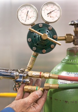
Since the pressurized oxygen continues to flow as a narrow, penetrating stream some distance from the tip, it allows you to accurately control the cut simply by aiming the torch in the direction where you want the cut. The burnt metal (slag) is either blown away as red-hot particles or it may adhere to the underside of the cut surface. You will immediately notice the difference in appearance between the base plate metal and slag.
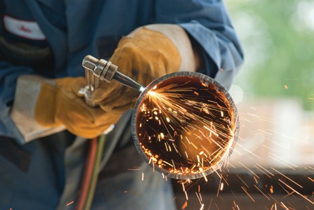
With the variety of oxyacetylene cutting torches available, sheet metal as thin as 0.8 mm ([latex]\frac{1}{32}[/latex] in.) and plate steel as thick as 600 mm (24 in.) can be accurately cut. The majority of cutting is done on plate ranging from 2 to 50 mm ([latex]\frac{1}{8}[/latex] in. to 2 in.) thick.
Not all metals can be successfully cut by this process. Metals that contain iron, such as low carbon steel and wrought iron, can be cut without difficulty. Metals that contain no iron (non-ferrous alloys), such as aluminum, copper or brass, cannot be cut with the oxyacetylene process.
Setting Pressures
- Make sure the cylinder valves are open and the regulator pressure-adjusting screws are turned out all the way before setting working pressures.
- Select and install the appropriate cutting tip. The tip may already be installed, but make a note of the cutting tip size. Remember, the thickness of the metal to be cut has a direct bearing on tip size, and tip size has a direct bearing on working pressure. Refer to the manufacturer’s chart for correct settings.
- Before setting working pressures, make sure the preheat oxygen valve on the cutting attachment is closed. Then open the oxygen valve on the torch handle all the way.
- Open the acetylene torch valve no more than [latex]\frac{1}{2}[/latex] turn, and then turn in the pressure adjusting screw on the acetylene regulator until the gauge reads the selected working pressure. After adjusting, close the acetylene torch valve.
- Open the preheat oxygen valve [latex]\frac{1}{2}[/latex] turn, then turn in the pressure adjusting screw on the oxygen regulator until the gauge reads the selected working pressures. After adjusting, close the preheat oxygen valve.
Lighting and Adjusting the Flame
- Equip yourself with appropriate personal protective equipment (PPE), including coveralls, heavy leather gloves, boots, shaded safety goggles, and a welding cap. Be careful where you point a lit torch and where you let slag deposit once you begin to cut.
- Before lighting the torch, ensure that there is adequate ventilation, particularly if the metal to be cut is coated with primer or other treatment.
- To light the torch, open the acetylene valve on the torch handle no more than [latex]\frac{1}{2}[/latex] turn and ignite the gas at the tip using a striker. The flame will be long and yellow. Adjust the valve until most of the smoke clears from the flame. Never attempt to light a flame with any other form of ignition other than a striker (e.g., matches or lighters).
- Slowly open the pre-heat oxygen valve. You will immediately notice the flames change in colour from yellow to blue.
- Adjust the preheat oxygen valve to a neutral flame. The torch is now adjusted and ready to use for cutting.
Extinguishing the Flame
- To extinguish the flame, first close the acetylene torch valve. The flame will go out but oxygen gas will continue to flow from the tip.
- Close the preheat oxygen valve on the cutting attachment to temporarily stop the flow of oxygen. The torch can be left for a short time (10 minutes or less) in this state. Whenever work is stopped for a longer period, bleed the system completely.
Torch Position and Motion
If the plate is 13 mm ([latex]\frac{1}{2}[/latex] in.) thick or greater (Figure 3a), the cutting tip should be held vertically to the plate at a 90° angle. For plate 6 to 13 mm ( [latex]\frac{1}{4}[/latex] in.) to [latex]\frac{1}{2}[/latex] in.) thick (Figure 3b), the cutting tip should be angled 60° to 70° back in the direction opposite the cut. This allows an increase in the cutting speed and helps prevent a buildup of slag underneath the plate. For plate less than 6 mm ([latex]\frac{1}{4}[/latex] in.) thick (Figure 3c), angle the tip 15° to 20°.
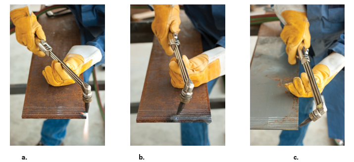
Before lighting the torch, practise the cutting motion to become familiar with the required body and hand positions. Note the placement of the hoses. They should not lie where sparks or slag from the cutting operation could land on and burn them. Keep them well out of the way, preferably behind you, and away from sharp edges or heat sources. Do not use your body or arms to support them. Take any twist out of the hose.
With goggles and gloves on, hold the torch in your right hand*, with your thumb on the cutting lever. Rest the outside edge of your left hand about 150 mm (6 in.) from the line to be cut and support the torch with your thumb and index finger.
(Note that the positions suggested here are for right-handed operators.)*
Ensure that you are not positioned directly above the plume of the cutting torch. Placing your head to one side of the cutting line will reduce the amount of exposure to the metal fumes being produced and will allow you to better see the tip of the torch. Ensure that the ventilation takeout fitting is positioned opposite the material from you so as not to draw the fumes toward your breathing zone.
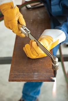
Guide the torch with your right hand, and support it with your left. With the left hand acting as a pivot, swing the torch from one side of the plate to the other. The torch should always be moved away from you, rather than toward you. You will notice that the cutting tip moves in a wide arc. To make a straight cut, you must perfect the technique of sliding your left hand and the torch in such a way that the cutting nozzle stays on a straight line. On a dry run (without the torch lit), hold the torch so that the tip is pointing straight down, midway between the two ends of the cut line.
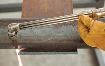
Roll your left hand forward and to your right, to bring the tip directly over the starting point of the cut.
Steadily roll your left hand, from right to left and use your right to guide the tip along the cut line. Continue to roll and guide the torch until you reach the end of the line (Figure 6). The tip should remain approximately 10 mm ([latex]\frac{3}{8}[/latex] in.) above the surface of the plate at all times.
This roll may seem a little awkward and unnatural at first, but with practice, it will become easy. It is important to be comfortable and have full control of the torch. The same motion is used when making very long cuts, but it may be necessary to stop cutting and reposition yourself several times. Keep in mind that the angle of the tip should change according to the thickness of the metal.
Starting Methods
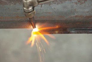
Several methods can be used to start a cut at the edge of a work piece. The most common is to place the tip halfway over the edge of the plate, steadily holding the ends of the preheat flames about 3 mm ( [latex]\frac{1}{8}[/latex] in.) above the plate surface. When the edge reaches a cherry-red colour, slowly depress the cutting oxygen lever to start the cutting process.
Another method is to put the entire tip over the edge of the material to be cut, then move it back and forth a short distance along the line of the cut until the material is cherry red in colour. Move the tip back from the edge, depress the cutting lever, and then slowly move toward the material to begin the cut. This method has the advantage of producing sharper corners at the beginning of the cut and reducing slag buildup on the underside.
Once the cut has been started (the cut is all the way through), move the torch along the line of cut with a smooth, steady motion. Maintain a constant tip-to-work distance as closely as possible. Move the torch at a speed which produces a light ripping sound and a smooth spark stream.
Cutting Results
Examine the surface on the edge of a cut plate to determine the quality of the cut and the performance of the torch. The following examples show possible cutting results as they appear on the plate edge. Use these as a reference when cutting plate.
Correctly Made Cut
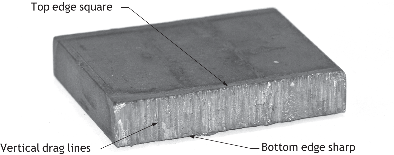
On a good cut, drag lines (lines created by the cutting action on metal) are vertical and not too pronounced. The top edge should be square, and any slag is easily removed. The bottom edge should be sharp.
Cutting Speed Too Slow
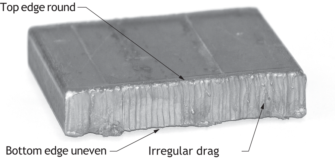
On a cut made too slowly, the drag line will be irregular, the bottom edge will be uneven, and the top edge will be rounded. Too much cutting oxygen for the cutting speed is the cause, possibly from an oversized tip, incorrect pressure setting, or poor technique.
Cutting Speed Too Fast
On a cut made too quickly, the drag lines are curved, slag adheres to the bottom edge, the top edge is sharp, and the cut face is smooth. When not enough heating is used to complete the cut, slag will collect.
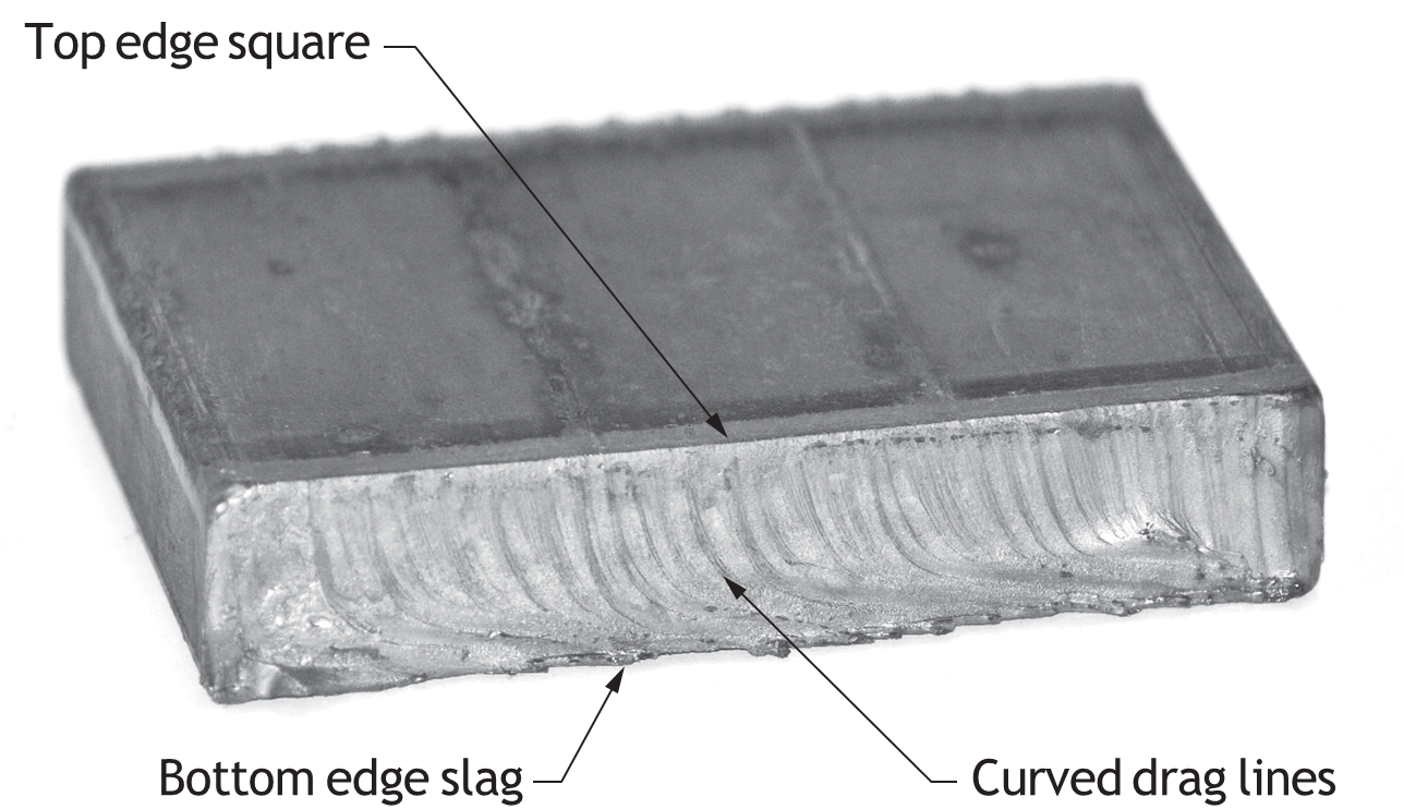
Dirty Tip Used
On a cut made with a dirty tip, drag lines are irregular, the cut face is rough, slag is excessive and control is poor while cutting. These problems are caused by dirt or slag in the tip deflecting the oxygen jet and reducing cutting efficiency.
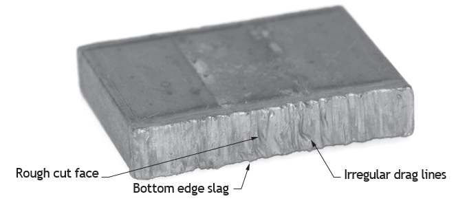
Factors that are important in achieving a quality cut are:
- Working pressure settings
- Amount of preheat flames
- Angle of torch tip relative to metal
- Tip size
- Speed of cutting torch across metal
- Control of torch by operator
After making a few cuts, see your instructor for an evaluation of the cuts. The instructor may suggest adjusting the torch or the pressures, or perhaps altering your grip or the motion of the torch. Your instructor can provide helpful hints to aid you in achieving quality results.
Precautions with Containers
A common task is the potentially dangerous cutting and welding of tanks and containers. Combustible gases and solid residues make containers potential bombs unless they are carefully prepared before cutting or welding. Work involving flame or sparks should never be done on barrels, drums, tanks or other containers until they have been thoroughly cleaned to ensure that no flammable solids, liquids, or vapours remain and the container has been verified safe.
Fuel must combine with oxygen and have a form of ignition for a fire or explosion to occur. Most liquids and solids do not explode until they have been heated and vaporized into gases. Even a gasoline tank that contains no liquid gasoline can have enough vapour present to cause an explosion if ignited.
The importance of using correct procedures and precautionary measures to ensure that fires or explosions do not occur cannot be over-emphasized. The various methods used for cleaning containers, such as steaming, boiling or purging, should be done only by qualified individuals using specialized equipment.
If you are asked to cut or weld a container that you suspect may have contained a combustible substance, do not assume that the proper procedures for preparing the container have been completed. Do not proceed to cut or weld unless you are absolutely sure all necessary precautions have been taken.
Note: Do not attempt to weld or cut, smoke near, or bring a light into any tank or enclosure that contained gasoline or any other flammable material unless the space has been thoroughly purged and inspected.
Precautions with Oxyacetylene Equipment
When using oxy-acetylene equipment it is important to observe the following safety precautions:
- Never use cutting or welding torches where sparks or an open flame of any kind would be a hazard. If possible, take the workpiece to a location where there is no possibility of setting fires. If the workpiece cannot be moved, remove any flammable material, including matches from your pocket. When necessary, use sheet metal guards or flame-resistant curtains to contain sparks.
- Butane lighters are potentially explosive and should never be in your possession when welding or cutting.
- Keep sleeves and collars buttoned at all times. Avoid pants with cuffs and shirts with rolled- up sleeves or open pockets into which sparks may fly. Avoid greasy or oily clothing.
- Be sure to keep a clear space between the cylinders and the work. This is important in case the regulators need to be reached quickly.
- Always test an outfit for leaks before use.
- Never cut or weld any material on concrete, as concrete may explode when heated.
Soldering and Brazing
The basic principles behind soldering and brazing are adhesion, cohesion, state change, and capillary action. Properly cleaning the tube and fittings and applying flux prepares the copper for the filler alloy to adhere to the surface of the copper. As the alloy is heated, it changes state from a solid to a liquid. The flux wets the alloy and reduces its surface tension, allowing it to flow readily into the joint. Capillary action draws this free-flowing liquid alloy into the annular space between tube and fitting. The filler alloy, once cooled, has strong cohesive properties to create a physical bond able to withstand the pressure of the system and resist physical damage.
Copper tube and fittings may be joined in a number of ways, depending on the purpose of the system. Soldering and brazing with capillary fittings are the methods used most.
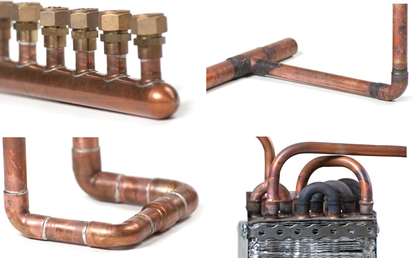
The American Welding Society (AWS) defines soldering as a joining process that takes place below 449 °C (840 °F) and brazing as a similar process that occurs above 449 °C (840 °F) but below the melting point of the base metals. In actual practice for copper systems, most soldering is done at temperatures from about 177 °C (350 °F) to 288 °C (550 °F), while most brazing is done at temperatures ranging from 593 °C (1100 °F) to 816 °C (1500 °F).
Potable water systems are often soldered as are hydronic heating and compressed air. Medical gas systems, fuel gas systems, and refrigeration systems are all brazed. As well, potable water underground must be brazed.
Definitions
alloy: A homogeneous metal composed of two or more elements.
capillary action: When liquid solder is drawn into the annular space between the inside fitting wall and the tubing’s outside wall because there is a stronger attraction (adhesion) between the copper and the liquid solder molecules than between the solder molecules themselves (cohesion).
solidus: The temperature at which 100% of the alloy is in a solid, crystalline form.
liquidus: The temperature at which 100% of the alloy is in a fluid, non-crystalline form.
plastic range: Also called the pasty range, the plastic range is the temperature range between the solidus and liquidus of an alloy; some portion of the alloy is solid, but the majority is liquid. This is due to the alloy’s components solidifying at different temperatures.
eutectic alloy: Alloys are eutectic when the solidus and liquidus points are the same. The opposite of having a plastic melting range, eutectic alloys solidify at a single, sharp temperature.
Abbreviations
Sn—tin
Pb—lead
Ag—silver
Ni—nickel
Cu—copper
Sb—antimony
Cd—cadmium
Zn—zinc
Soldering and Brazing Uses
- Potable water systems—residential, commercial and industrial
- Refrigeration tubing (silver brazing only)
- Fire sprinkler systems
- Extracted tee joints
- Drainage, waste and venting systems
- Medical gas systems (silver brazing only)
Solder Filler Metals
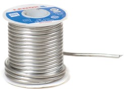
Soft soldering filler metals are a group of filler metals with melting temperatures below 800OF.
They are available in [latex]\frac{3}{64}[/latex] in., [latex]\frac{1}{16}[/latex] in., [latex]\frac{3}{32}[/latex] in. and [latex]\frac{1}{8}[/latex] in. diameter, 1 lb. spools. Other diameters and spool sizes are available from manufacturers on request.
50/50, 40/60, 60/40 Tin/Lead
With some exceptions, the tin/lead (i.e., 60/40 = 60% tin and 40% lead) solders can be used to solder copper and most copper alloys, lead, nickel alloys and steel.
Tin-lead solders are not recommended in high stress or vibration joints in the cooling industry due to lack of sufficient elongation properties. It is illegal to use lead alloys in connection with potable water systems. (Refer to lead-free solder information). 40/60, 60/40, and 50/50 solders are also available with rosin or acid cores.
95/5 Tin/Antimony
The 95/5 tin/antimony lead-free solder is useful for applications where moderately elevated temperature is a factor. With a higher electrical conductivity and high fluidity, 95/5 is recommended for lead-free installation of small-diameter, tight-fitting connections. The tin/ antimony solders are not recommended for use on brass.
Lead-Free Solders
Lead-free solders were developed to conform to regulations banning the use of lead-based solders with over 0.2% lead in potable water systems. This non-toxic solder alloy typically exceeds the physical advantages of lead-tin solders. Lead-free solders may contain all of or parts of the following metals: specific amounts of silver (Ag), antimony (Sb), copper (Cu), nickel (Ni) and or tin (Sn). The strength of a lead-free solder joint will normally exceed the pressure point at which copper tubing will burst.
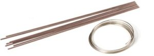
Brazing Filler Metals (Hard Solders)
Brazing alloys have two general categories:
- BAg containing primarily copper and varying amounts of silver with some other minor elements.
- BCuP comprised mostly of copper, with added phosphorus to act as a flux. Some BCuP alloys may contain small amounts of silver for added strength.
Copper tube and solder-type pressure fittings are accurately made for each other, and the tolerances permitted for each assure the capillary space will be within the limits necessary for a joint of satisfactory strength, regardless of whether you are soldering or brazing.
Brazing Copper Silver Alloys (BAg)
[B = Brazing/Ag = Silver] Used for high-temperature applications, loose tolerance situations and for dissimilar metals. Many contain cadmium (a highly toxic element) so treat these alloys with caution and wear proper Personal Protective Equipment. BAg is not used as commonly in the pipe trades as BCuP.
Brazing Copper Phosphorous Alloys (BCuP)
[B = Brazing/Cu = Copper/P = Phosphorus] Copper/phosphorous and copper/silver/phosphorous alloys are used to braze copper to copper and copper to brass. The phosphorus content in these alloys makes them self-fluxing on copper. When brazing brass or copper to brass, a brazing flux must be applied. BCuP alloys are not recommended for brazing steel or other ferrous metals.
Fluxes
Soldering fluxes are classified as corrosive, intermediate, or non-corrosive. The choice may depend on the metals being joined and the melting range of the alloy. Fluxes can be either petroleum based or water based.
Although brazed joints may not always require the application of a flux, soft solder joints will always require a flux to be applied to the metal surfaces prior to heating, primarily to remove any minor surface impurities. As the material is heated, fluxes prevent the formation of oxides, which may contaminate the joint. They also assist the flow of alloy into the capillary spaces of the cup and tube.
Different fluxes perform these duties in various ways and at different temperatures.
Soft Solder Flux (Petroleum Based)
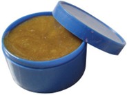
Petroleum-based paste fluxes are basically made up of organic chlorides, zinc, bromides, fluorides and ammonium chlorides mixed in a petroleum-grease base. Because of their corrosive properties, it is necessary to properly limit the amount of flux entering the joint and to thoroughly clean the exterior after soldering to avoid further oxidation and visible discolouration.
Soft Solder Flux (Water Based)
Water-based fluxes are a newer development in fluxes in response to a need for materials that have less environmental impact. Many of these new fluxes are more sensitive to being heated within the temperature ranges in which petroleum-based fluxes are used. Care must be taken to avoiding charring the flux, as it has less tolerance to overheating than petroleum flux.
The active temperature range for these soft solder fluxes is between 200°F (93°C) and 600°F (315°C).
Composition:
- Chlorides
Precautions
- Fumes and gases can be hazardous to your health. Burns eyes and skin on contact.
- Can be fatal if swallowed.
- Before use, read and understand the manufacturer’s instructions, the Material Safety Data Sheet (MSDS), and your employer’s safety practices.
- Keep your head out of fumes.
- Use enough ventilation, exhaust at the flame, or both, to keep fumes and gases from your breathing zone and the general area.
- Avoid contact of flux with eyes and skin. Wear safety glasses and gloves.
- Do not take internally.
First Aid
- If contact with eyes, flush immediately with water for 15 minutes.
- If swallowed, induce vomiting.
- Never give anything by mouth to an unconscious person. Call a physician.
Brazing Flux
White brazing paste flux is an effective and efficient flux for use in silver brazing most ferrous and non-ferrous metals except aluminum, magnesium and titanium. Recommended filler metals for use with white brazing flux include those of BAg and BCuP classification.
The shelf life of these types of fluxes is approximately 1 year from the time of manufacture.
The active temperature range for brazing flux is between 566°C to 871°C (1050° to 1600°F).
Composition:
- Water
- Boric acid
- Potassium fluorides
Precautions
- Contains fluorides.
- Fumes and gases can be hazardous to your health. Burns eyes and skin on contact.
- Can be fatal if swallowed.
- Before use, read and understand the manufacturer’s instructions, Material Safety Data Sheet (MSDS), and your employer’s safety practices.
- Keep your head out of fumes.
- Use enough ventilation, exhaust at the flame, or both to keep fumes and gases from your breathing zone and the general area.
- Avoid contact of flux with eyes and skin.
- Do not take internally.
- Keep children away when using.
First Aid
- If contact with eyes, flush immediately with water for 15 minutes.
- If swallowed, induce vomiting.
- Never give anything by mouth to an unconscious person. Call a physician.
Soldering and Brazing Using Air-Acetylene
Size B Acetylene Tank Specifics
- Holds 40 cubic feet of pure acetylene gas (the smaller tank, size “MC” holds 10 cubic feet). Note: These capacities represent the volume of fuel available at standard atmospheric pressure (14.73 psia) and temperature (70°F). The B tanks’ true internal volume is actually 0.61 ft³.
- Tank is normally supplied with a protective plastic cap or shield over the outlet to prevent the entry of debris before the regulator and hose are connected.
- Tank has fusible (liquefiable), temperature-sensitive plugs, which release excessive pressures when activated.
- Requires no oxygen cylinder; the oxygen required to support combustion is supplied from the air surrounding the torch tip.
- Produces a flame with temperature of about 4000°F—hotter than gases such as Butane, Propane and Natural Gas.
- Tank is packed with a porous material called agamassan (a porous material such as asbestos, charcoal or diatomaceous earth) that is saturated with acetone (acetone has the ability to dissolve many times its own volume of acetylene), so that there is no free unstable gas in the tank. It is therefore gas dissolved in liquid—but when pressure is released in the cylinder, the acetylene boils off.
- The pressure inside a fully charged tank at 70°F is approximately 250 psi. At higher temperatures the pressure will be also be higher; at lower temperatures, it will be lower, but these pressure variations have no effect on the quantity of gas in the tank. However, the amount of pressure change caused by a change in temperature varies according to the amount of acetylene in the tank.
- The newer versions of the tank have a regular wheel handle shut-off valve at the top. Older versions only have a square valve stem that needs a valve key to open and close the valve. Or the square hole in a tubing cutter reamer can be used.
- Never use pliers to open the tank valve; the valve stem will be damaged.
- Use the tank in the upright position.
- If acetone appears from the tip (purple, hazy flame), it is typically due to the tank having been laid on its side. Allow the bottle to sit upright for 24 hours before attempting to re-light. Contact the supplier if problems persist.
B and MC Tank Equipment
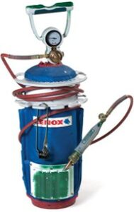
- Tips come in a variety of sizes. Tips are selected based on the required amount of heat for the job. A larger tip provides more heat than a smaller tip. For most brazing jobs, acetylene-air or B tanks will suffice. Always refer to the manufacturer’s literature for correct tip size selection.
- The tank hose is typically [latex]\frac{3}{16}[/latex] in. in diameter and is available in 6, 12 and 25 ft lengths.
- Torch handle has a control valve for on/off command.
- The pressure regulator is equipped with a pressure regulating adjustment that allows a variable delivery pressure of up to 13 psi.
- A gauge displays the gas content (volume) at all times.
- A gauge to display working pressure (delivery pressure) is sometimes present, or can be added.
- A metal filter, located in the inlet of the regulator, prevents dirt or foreign particles from entering the regulator from the tank.
Setting Up the B Tank
- Secure the tank.
- Have fire protection equipment ready, including fire shields to protect nearby surfaces.
- Remove the protective shield on the tank outlet, and open the tank valve briefly to clear any debris that may be lodged in the tank outlet.
- Install the regulator, hoses, handle and tip. Excessive force must not be used on connecting nuts. Care must be taken not to damage the pressure regulator.
- Make sure that the pressure regulator connecting nut and all hose and handle coupling nuts are secure. Do not allow the hose to come in contact with flame, sharp objects, oil or grease.
- Open tank valve on half turn and test connections with soap and water to make sure there are no leaks.
- Select the right size tip.
- Turn the control all the way on at the pressure regulator.
- Open the needle valve on the torch handle slightly and light it with a flint lighter.
- Adjust flame to the required amount at the tank regulator with the torch handle control valve fully open.
- If the flame should blow out, re-light the torch and adjust the regulator accordingly (clockwise for more flow).
- If you smell acetylene gas at any time, check for leaks immediately.
Soldering and Brazing Procedures
The following instructions and techniques will aid in producing quality, leak-free soldered or brazed joints when connecting copper tube and fittings.
The procedures for soft soldering are similar to those for brazing. Above all, cleanliness is most important to avoid joint contamination and possible failures. Fluxes used for either process must be compatible with the temperatures involved, and flux may not be required under some circumstances (for example, copper-to-copper joints using BCuP alloy).
- Safety Precautions
Always observe the following safety procedures when using soldering and brazing equipment:
- Wear eye protection and hand protection.
- Work in a well-ventilated area when possible.
- If the joints to be sweated (soldered) are near combustible materials, such as a wall or floor of a building, use a shield such as a fireproof board between the joints and the combustible material. Use care to avoid causing a fire with the torch.
- Always have a charged and appropriate fire extinguisher on hand. Have a hot-work permit, if required.
- Avoid contact with molten solder.
- Measurement
Measure and mark the tube with a pencil or marker. Remember to allow for the length of tube that fits into the fitting cup. Dry-fitting the tube and fittings before soldering will ensure that the fittings are square and the runs straight. - Cutting
The tube is best prepared when cut with a rotary tubing cutter. Care must be taken that the tube is not deformed while being cut. If you are installing soft temper tube (annealed tube), you must be especially careful to not deform the tube end by applying too much pressure when cutting. Regardless of the method, the cut must be square to the run of the tube so that the tube will seat properly in the fitting cup.
- Reaming
Ream all cut tube ends to the full inside diameter of the tube to remove the small burrs created by cutting. If the rough inside edge is not removed by reaming, erosion corrosion may occur due to local turbulence and increased local flow velocity in the tube. A properly reamed piece of tube provides a smooth surface for better water flow. Also remove any burrs on the outside of the tube end created by the cutting to ensure proper entrance of the tube into the fitting cup. Tools that can be used to ream the tube end include the reaming blade on some tubing cutters, half-round or round files, a pocketknife or a suitable de-burring tool. - Cleaning
The removal of all oxides and surface oils from the tube end and fitting cup is crucial to encourage proper flow of solder metal into the joint. Failure to remove them can interfere with capillary action and may lessen the strength of the joint. There are two methods of cleaning:
- Mechanical cleaning of surfaces can be accomplished by filing, brushing or scouring. Scouring the tubing and larger fittings with a product like sand cloth is the most common way to mechanically clean copper, brass and other soft metals. Smaller fittings, typically 1 in. and under, are often cleaned internally by a stainless steel fitting brush. Never use steel wool as it often contains contaminants.
- Chemical cleaning uses solvents or alkali substances for the removal of oils or grease. Carbon tetrachloride, trichloroethylene or methyl chloroform may be used. Chemically pickling uses an acid-bath for the removal of rust, scale and oxides from pipe and fittings. Acids such as hydrochloric, nitric and sulphuric acids are sometimes used. Note: Strong chemical cleaning is highly corrosive to copper and brass and must be neutralized to protect the piping system. It is not the common method and is prohibited for use by modern plumbing codes.
Lightly clean the tube end and fitting socket using open-mesh sand cloth or emery cloth for a distance slightly more than the depth of the fitting cup. The capillary space (annular space) between the tube and fitting is approximately 0.004 in. Solder metal is drawn into this gap by capillary action. This spacing is critical for the solder metal to flow into the gap and form a strong joint. Copper is a relatively soft metal. If too much material is removed from the tube end or fitting cup, a loose fit may result in a poor joint
- Inert Gas Purge
Some systems, such as medical gas and refrigeration systems, require the brazing process to be conducted under an oxygen-purged condition. This is accomplished by pumping an inert gas such as nitrogen or argon through the piping during the brazing process, purging any oxygen and thereby eliminating the potential for oxidation. This condition occurs when materials are heated with oxygen available and oxides are created. These impurities, such as copper oxide, collecting on the surface of the tube, both inside and out. If this flaky by-product is permitted to be created inside the system, it could then damage components or in the case of medical gas, result in a life- threatening contamination. - Applying Flux
Use a flux that will dissolve and remove traces of oxide (which is usually blackish or greenish in colour) from the cleaned surfaces. This will protect the cleaned surfaces from re-oxidation during heating and promote wetting of the surfaces for the solder metal. It is important to use fluxes that conform to the ASTM B 813 standard so that any flux residue left inside the system will flush out with water. Apply a thin, even coat of flux with a brush to both the tube and fitting immediately after cleaning.
Note: Do not apply the flux with your fingers.
Chemicals in the flux can be harmful if they come into contact with the eyes, mouth or open cuts. Careless workmanship can cause problems long after the system has been installed. If excessive amounts of flux are used, the flux residue can cause corrosion. In extreme cases, such flux corrosion could perforate the wall of the tube, the fitting or both. - Assembly and Support
Insert the tube end into the fitting cup, making sure the tube is seated against the base of the fitting cup. A slight twisting motion ensures even coverage by the flux. Remove excess flux from the exterior of the joint with a cotton rag. Align, square and support the tube and fitting assembly to ensure a uniform capillary space around the entire circumference of the joint. Uniformity of capillary space will ensure good capillary flow of the molten solder metal. Excessive joint clearance can lead to solder metal cracking under conditions of stress or vibration. The joint is now ready for soldering. Joints prepared and ready for soldering must be completed as soon as possible (preferably the same day) and should not be left unfinished overnight. - Heating
Begin heating with the flame perpendicular to the tube. The copper tube conducts the initial heat into the fitting cup for even distribution of heat in the joint area. The extent of this preheating depends on the size of the joint. Preheating of the assembly should include the entire circumference of the tube in order to bring it up to a suitable temperature. Next, move the flame onto the fitting cup. Sweep the flame alternately between the fitting cup and the tube a distance equal to the depth of the fitting cup. Practice and experience will indicate the amount of heat and time needed. Observe the reaction of the flux as the heat is applied. The reaction of the flux will give some indication of the temperature when you arrive at the temperature to apply the filler metal. Soft solder fluxes look and react differently than silver brazing flux. Petroleum-based fluxes will show smoke, indicating that the joint is near a temperature that is adequate to attempt to introduce filler alloy. Be careful not to overheat the flux at this point. Touch the solder to the joint where the tube meets the hub of the fitting. If the solder does not melt, remove it and continue heating. Do not attempt to melt the solder with the torch flame. The alloy must be introduced to the joint by the heat of the fitting and tube itself. Avoid overheating the joint or directing the flame into the face of the fitting cup. Overheating could burn the flux, which will destroy its effectiveness. Also, the solder will not properly enter the joint. When the solder melts, apply heat to the base of the cup to aid capillary action in drawing the molten solder into the cup toward the heat source. Once the entire joint is heated to the point where the solder alloy flows smoothly, remove the flame from the joint in stages in order to maintain the desired amount of heat without continuing to increase the joint’s temperature. Cap the entire circumference of the joint to make certain that no voids exist. Control of temperature can be a key to filling trouble spots. You may need to cool and re-clean an area that is difficult to fill. - Cooling and Post-Cleaning
Allow the completed joint to cool naturally to below its plastic (pasty) range, as shock-cooling with water may stress the joint. As soon as the joint is cool, to be sure to clean off remaining flux residue with a damp rag. When soft soldering, excess solder may be visible outside the joint. Part of your duty as a tradesperson requires that you take great pride in your ability and the appearance of your work. While the joint is still molten, use the end of the solder metal to sweep the excess solder off, or carefully wipe the joint with a clean, dry rag. However, be careful not to bump or disturb the joint while the solder filler metal is still molten. Moving the joint before the solder has cooled to below its pasty range can cause internal stresses that weaken the joint. These added stresses may show up some time down the road as hairline cracks that will cause the joint to “weep.”
 Self-Test B-5.2: Describe Cutting, Brazing and Soldering Techniques
Complete Self-Test 5.2 and check your answers.
If you are using a printed copy, please find Self-Test A-5.2 and Answer Key in the Appendix at the end. If you prefer, you can scan the QR code with your digital device to go directly to the interactive Self-Test.

References
BC Industry Training Authority. (2019). Piping trades apprenticeship program: Use Tools and Equipment—Level 1 harmonized [Binder]. Crown Publications, Queen’s Printer for British Columbia. https://www.crownpub.bc.ca/Product/Details/7960000261_S
Industry Training Authority. (2019). Piping trades apprenticeship program: Level 1—Competency B-4: Use soldering and brazing equipment (Sprinkler fitter). Crown Publications, Queen’s Printer for British Columbia.
Industry Training Authority. (2019). Piping trades apprenticeship program: Level 1—Competency B-5: Use cutting, brazing and soldering equipment (Plumber). Crown Publications, Queen’s Printer for British Columbia.
Industry Training Authority. (2019). Piping trades apprenticeship program: Level 1—Competency B-6: Use oxy-fuel cutting equipment (Plumber). Crown Publications, Queen’s Printer for British Columbia.
Industry Training Authority. (2019). Piping trades apprenticeship program: Level 1—Competency B-6: Use soldering and brazing equipment (Steamfitter). Crown Publications, Queen’s Printer for British Columbia.
Industry Training Authority. (2019). Piping trades apprenticeship program: Level 1—Competency B-7: Use oxy-fuel equipment (Steamfitter). Crown Publications, Queen’s Printer for British Columbia.
Media Attributions
All figures are sourced from Industry Training Authority (2019) and/or Camosun College (2019) and are used under the Creative Commons Attribution 4.0 (CC BY 4.0) licence unless otherwise noted. Images copyrighted by the BC Industry Training Authority are licensed under a Creative Commons Attribution-NonCommercial-ShareAlike 4.0 (CC BY-NC-SA 4.0) licence.
The width of material removed by a cutting tool such as a saw blade. (Section B-1.1; Section B-2.2)
A flame with the right mix of oxygen and fuel so it burns clean and does not damage the metal. (Section B-5.1)
A hard residue left on a weld after metal is melted and fused together. (Section B-1.1)
The way a liquid (like melted solder) is pulled into small spaces between two surfaces without being pushed. (Section B-5.1)
A substance used in soldering or brazing to clean metal surfaces and help melted metal flow smoothly into a joint. (Section B-5.1)
A property of some metals or filler materials that allows them to clean and protect the joint without needing a separate flux, helping the molten metal flow properly during brazing or soldering. (Section B-5.2)
The temperature range where a metal is partly solid and partly liquid, making it soft and easy to shape. (Section B-5.1)