B-6.3 Describe the Arc Welding Process and Equipment
Principles of SMAW
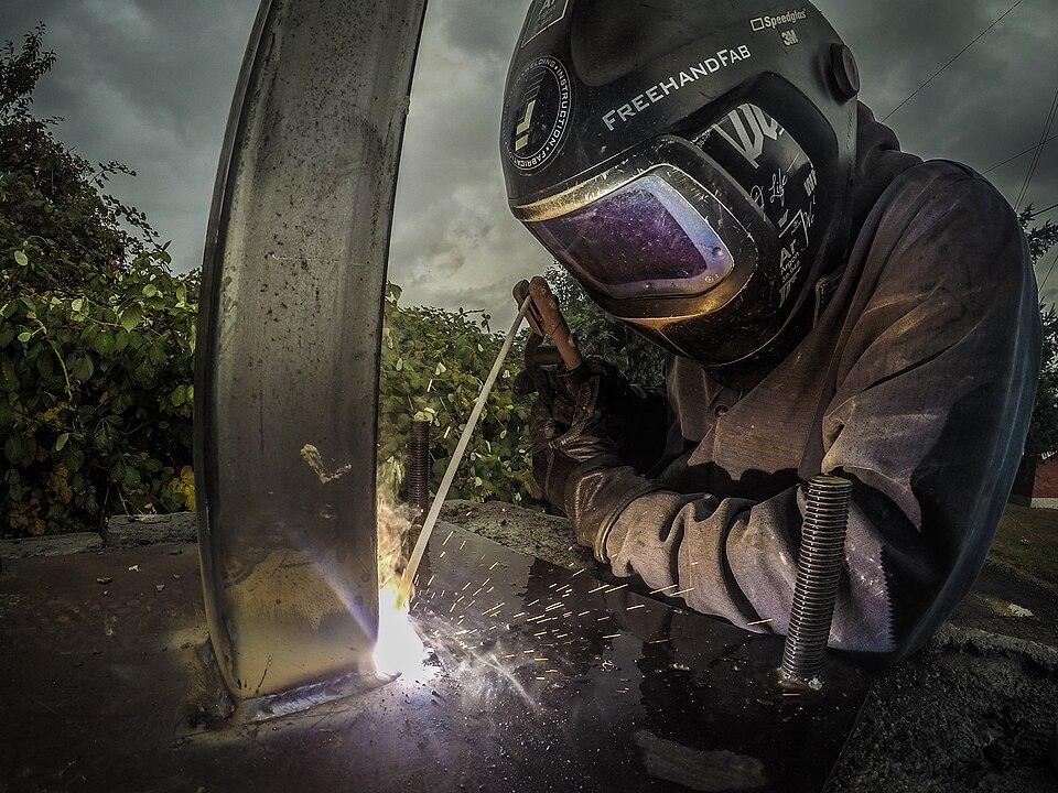
Shielded metal arc welding (SMAW) is commonly referred to as stick welding or electric arc welding. An electric arc is the bridge of light and heat that develops when an electric current is forced to leap across a small gap that has been formed in an electric circuit. In the SMAW process, the welding equipment is designed to maintain this arc, and the metals are fused by the intense heat the arc generates.
The flow of electricity in an electric circuit is comparable in many ways to the flow of water in a pipeline. Water flows from a tap because there is pressure in the system. This pressure forces the water to flow through the pipes. The greater the pressure, the more water will flow through a given pipe. The pressure of water in a system is measured in kilopascals (kPa) or in pounds per square inch (psi). The flow of water is measured in cubic metres per hour (m3/h) or in cubic feet per hour (ft3/h).
The electricity that flows through the conductors of an electric circuit does so because there is electrical “pressure” created by a generator at the power source. This electrical pressure is called voltage and is measured in volts (V). The flow of electricity is called current and is measured in amperes (A).
To do useful work, an electrical current must flow through the conductors in a closed electrical circuit. If for some reason this circuit is broken (or opened), the flow of electricity will stop. Electrical pressure (voltage) will continue to exist while the generator runs, and current will resume as soon as the circuit is completed (closed) again. An arc welding circuit is basically an electric circuit that the welder can close and open as required.
Applications of SMAW
Almost any requirement for welding mild and stainless steel and cast iron can be accomplished using the SMAW process. Its uses include:
- Shipbuilding
- Locomotive and boiler making
- Structural work
- Engineering applications
- Building
- Maintenance and repair of industrial and farm equipment
- Light gauge welding
- The assembly of automobiles
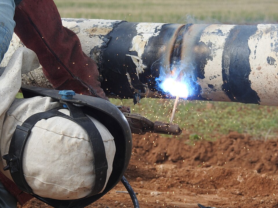
- The welding of pipelines
Power Source
The welding machine that provides the source of power for arc welding is an extremely important part of the process. Power sources for SMAW may supply either alternating current (AC) or direct current (DC). They also have controls so that the welder can vary the current to meet the requirements of different welding tasks, materials, and positions.
Alternating Current
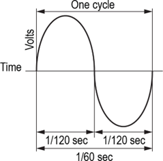
With AC, the direction of current flow rapidly reverses 120 times per second. A complete direction change from zero to maximum volts at one pole, then back to zero volts and up to maximum voltage at the other pole is called a cycle and occurs 60 times per second. Most electrical utility companies distribute alternating current at 60 cycles per second. This means that 60 times a second the voltage reaches a maximum in one direction, and 60 times per second it reaches a maximum voltage in the other direction.
Some of the characteristics of alternating current can be represented in the form of a sine wave diagram (Figure 3).
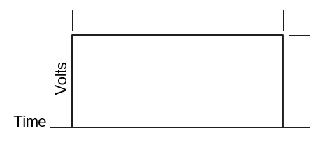
In comparison with the rapid fluctuations of alternating current, DC current flows from one pole continuously without fluctuation (Figure 4).
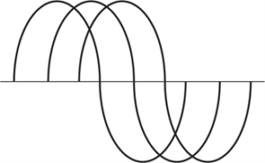
Alternating current may be single-phase AC (Figure 5) or three-phase AC (Figure 6).
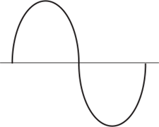
Single-phase AC power is useful for most domestic and light industrial operations. However, as Figure 5 shows, there is a considerable period of time during each cycle when less than maximum power is being delivered. This makes single-phase power inefficient for heavy industrial uses, including some welding applications.
Three-phase AC power is more often used for industrial jobs. Three-phase AC power utilizes three single-phase currents timed to start at regular intervals from each other (Figure 6). The advantage of three-phase power is that even though one phase may be delivering only minimum power, one of the other two phases will be delivering nearly maximum power. Welding machines that use three-phase power are generally more compact and produce a smoother arc than single-phase machines.
Direct Current
With direct current, the electrons in a circuit flow in one direction only from the negative to the positive pole. This type of current is produced by DC generators and by batteries.
Polarity
Electron flow in an electrical circuit is always from the negative pole to the positive. However, the practical effects of this for welding are more important with DC welding current (Figure 7). With direct current, the electron flow is in one direction only and, depending on how you connect the circuit, the current flow can be made to affect the heat of the electrode or of the workpiece.
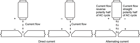
The polarity of a DC welding circuit can be used in two ways:
- DCEN (DC electrode negative) connects the welding circuit so that the electrode is attached to the negative pole of the power source to concentrate heat in the workpiece (Figure 8)
- DCEP (DC electrode positive) connects the welding circuit so the electrode is attached to the positive pole of the power source to concentrate heat in the electrode
When using coated electrodes in SMAW, DCEN (negative) generally allows for faster welding speeds and for higher filler rod deposit. It provides a medium depth of penetration. With DCEP (positive), the heat can be concentrated at the electrode. With this polarity, you can achieve a deeper penetration in the weld, but the welding speed is slower.
Controls
On most DC motor and engine-driven generators for SMAW, there are controls for both current and voltage levels. That way, the welder can alter the shape of the volt-amp curve and adjust the characteristics of the arc to suit the requirements of a particular welding task. These machines are called dual-control machines.
The controls may be of the tapped type (offering a range of specific settings) or the continuous control type that allow for infinite setting adjustment. On the tapped or stepped type of control, the dial must be set precisely on a given setting. Current values between settings cannot be obtained, and the device may suffer damage if you attempt to place the dial between settings. Instead, the fine adjustments that you require to accommodate the metal thickness, electrode size and type, and welding position for a given job are secured by using the fine adjustment control.
On machines with dual continuous controls, the coarse adjustment dial (sometimes known as the job selector dial) allows for continuous variation of current level. The second of the two controls allows for fine adjustment of the current and voltage. By manipulation of the two dials together, the slope of the volt-amp curve can be adjusted for any particular current level within the output range of the machine.
Fuel-Engine-Driven AC and AC/DC Welding Machines
A fuel engine can also be made to drive an alternator to produce AC current. As with the transformer/rectifier described earlier, some alternator machines feed the current into a rectifier to make DC current available in the same machine. The control devices on these welding machines are essentially the same as those described for the DC generators.
The Arc Welding Circuit
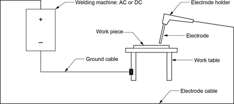
The SMAW welding circuit consists of:
- A power source
- A ground cable and clamp
- An electrode cable
- A welding electrode and electrode holder
- The workpiece
When the electrode is touched to the workpiece and then withdrawn a short distance, the arc is struck and the electrical circuit is completed. The current flows through the electrode, across the arc, through the workpiece, and through the ground clamp and cable, then returns to the power source.
The SMAW Process
When the power source for a welding circuit is turned on, but before the arc has been struck, the circuit is open. At this point, the voltage or the potential in the circuit is at its maximum and is called the “open-circuit voltage.” The moment the welder strikes the arc, the circuit is closed (completed), the voltage drops to what is called the “arc voltage,” and the high current in the welding circuit flows.
As the current crosses the arc from the electrode to the workpiece, tremendous heat is generated (anywhere from 5532 °C to 6632 °C). The heat melts the end of the electrode and the parent metal in the workpiece directly beneath the arc, forming a pool of molten metal. As the electrode melts, small particles of molten metal are carried across the arc stream and deposited in the molten pool on the parent metal, forming the weld deposit. This weld deposit is actually a mixture of the melted electrode and the melted parent metal. At the same time, the force of the arc digs into the workpiece and provides the necessary depth of penetration for the weld.
Electrodes
The electrodes used in the SMAW process are not bare but are covered with a flux. They have a core that consists of either a solid metal wire or a metal tube containing metal powders. The metal core conducts the electric current to the arc and provides the filler metal for the weld joint. This filler metal is deposited as the electrode is gradually consumed and as the welder moves the arc over the workpiece at the correct arc length and travel speed.
The coating of the electrode helps keep the arc stable and concentrated on a precise point on the weld. As the chemicals in the electrode coating are vapourized, they provide the shielding required to protect the molten metal from contamination by the atmosphere, hence the name “shielded metal arc welding.”
Welding electrodes are both fragile and expensive, so they require careful treatment. This treatment must be exercised both before and during the use of an electrode.
Handling of Electrodes Before and After Use
Handle electrodes with great care to avoid breaking or cracking the coating. An electrode that has received damage to the coating will usually perform poorly and, if pieces of the coating are actually missing, the result may be slag inclusion in the weld.
Because electrodes with very different properties may look the same, correct handling of electrodes also includes marking them accurately after the package has been opened. It is equally important to collect and clearly mark unused electrodes that are being returned to storage. Do not risk producing a weld that does not meet specifications because you used the wrong electrode. An electrode that is not clearly identified should be considered unusable.
Storage of Electrodes
A perfectly dry electrode is essential for a satisfactory weld. The main requirement for storage of electrodes is keeping them dry. In addition to being fragile, the composition of electrode coatings allows them to pick up moisture from the air. Prolonged exposure to moisture can result in disintegration of the coating. Even if the disintegration is not obvious, the heat of the arc will blow away portions of the coating. In either case, the electrode is rendered useless and must be discarded. Low-hydrogen electrodes must be thrown away if they have been directly exposed to water.
Moisture that is absorbed by an electrode contains hydrogen and, during welding, some of this hydrogen is transferred to the weld metal. This can lead to a number of problems with the weld. Depending on the composition of the base metal, these problems can include embrittlement, porosity, cracking of the weld, and a rough weld appearance. In addition, welding with a moist electrode increases the arc voltage, increases weld spatter, and makes slag removal difficult.
Some electrodes (such as mineral-coated ones) are more prone to absorbing moisture than others.
The length of time electrodes can be exposed to the atmosphere varies from 30 minutes to 4 hours or longer, depending on the relative humidity of the atmosphere. For example, with low-hydrogen electrodes, the maximum exposure time is between two and four hours, depending on the relative humidity. With all electrodes, it is impossible to tell simply by visual examination whether they have absorbed dangerous amounts of moisture.
To protect electrodes from moisture, manufacturers ship them in air-tight containers. Sealed portable containers are used on the job for storing the supply of electrodes.
Electrode Ovens
Some electrodes can be safely stored in normal room conditions, provided that temperature and relative humidity do not exceed certain normal tolerances. Electrode ovens are widely used to guarantee a humidity-controlled environment for storing electrodes. Ovens are essential for the more sensitive low-hydrogen and hardsurfacing types and for special alloy electrodes such as stainless steel, brass, bronze, aluminum, inconel and monel. Electrode ovens may be the large type found in welding shops capable of holding several hundred pounds of electrodes or the smaller field ovens that can be connected to an auxiliary power supply.
Ovens are also useful for restoring electrodes that may have been exposed to a certain level of moisture, but that can be rebaked to make them usable. Electrode manufacturers and suppliers provide information on storage and rebaking conditions for their electrodes and, if available, these recommendations should be followed.
Electrode Holder
The electrode holder (Figure 9) or “stinger” is the device used to carry the welding current to the welding electrode. It is also the means by which the welder holds the electrode while welding. The two most common types of electrode holder are the jaw type and the twist-head type. The jaw type grips the electrode between two jaws activated by a powerful spring. The twist-head type secures the electrode in place through the screw action of the head. The handle of any type of electrode holder is extremely well insulated to protect the welder against electric shock and heat.

Because it is the part of the welding circuit that the welder actually contacts, the electrode holder must be kept clean and in good condition to minimize any risk of shock. Replace any damaged insulation and clean the grooves of the jaw to remove any weld spatter that has collected.
The connection between the welding cable and the holder is a vulnerable point in the welding circuit because it is constantly being flexed during welding operations. This connection is usually mechanical and must be inspected every time you weld.
Ensure that the connection is tight. Loose connections increase electrical resistance and cause additional heat that can wear down insulation. Check the connection for broken strands of cable, as these too can cause heat buildup and can deteriorate the insulation. Should the connection have broken strands, cut off the damaged end and make a new connection, either mechanically or by soldering or brazing, before you start any welding.
Ground Clamps
At the other end of the welding circuit is the ground clamp or ground connection, which is necessary to make the welding circuit complete.
Without a good ground connection, there can be a loss of power through increased resistance, a risk of fire from sparking, and increased danger of electric shock.
The ground connection may be attached to a welding table or bench that is equipped with a permanently bolted or tack-welded lug or with an insulated terminal. If welding is not being done on a welding bench, the ground may be connected to the workpiece by means of a clamp. Clamps are of different types, the most common being the spring-loaded, C-clamp, rotary clamp, and magnetic clamp.
Electrode Stubs
Electrodes should be used down to a stub length of 50 mm (2″) or less. These electrode stubs should be disposed of in fireproof metal containers. If you throw them on the floor, they create a slipping hazard.
Slag
The coating that forms on the top of an arc weld is called slag. When it is first deposited it is very hot. It has to be removed after it has cooled and has become solid and hard. As you chip off slag, ensure that fragments do not hit you or anyone else.

Do not look directly into a laser beam! Looking directly into the beam may be hazardous to your eyes. A quick flash of the beam is not a problem, but prolonged exposure should be avoided. The instrument must be positioned either above or below the worker’s line of sight.
Portable Grinders
Grinders are used to prepare metal for welding, clean fresh welds, and remove weld faults to be re-welded.
When the workpiece is too large to bring to a bench or pedestal grinder, you can grind it by using a portable grinder. Portable grinders may be powered by compressed air or by electricity and are classed as either straight grinders or angle grinders.
Straight Grinders
Straight grinders are so named because the drive shaft, which turns the grinding wheel, is aligned with the motor (Figure 10).
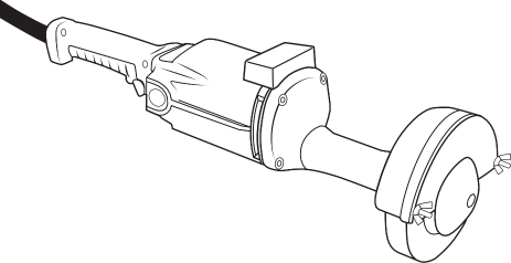
Straight grinders are available in a variety of sizes and shapes. Larger ones are used for the quick removal of metal, while small models are used in hard-to-reach areas.
The larger models of straight grinders have a grinding wheel approximately 150 mm (6″) in diameter. You must hold these larger models with both hands.
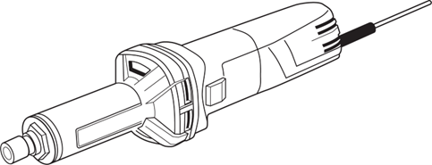
Small pencil grinders (die grinders), as illustrated in Figure 11, are used to remove small metal burrs from freshly drilled holes, for elongating holes and slots and for preparing material for welding in tight places. These grinders turn at very high speeds (25 000 revolutions per minute [RPM] or more).
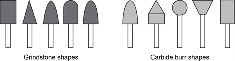
These small grinders use a small grinding stone or a carbide cutting burr mounted on their shafts (Figure 12).
Angle Grinders
Angle grinders have a grinding disk which rotates at 90° to the axis of the motor. This versatile tool comes in various sizes (Figures 13 and 14). Disks range in diameter from 75 mm (3″) to 225 mm (9″), and each disk type and size has its RPM rating identified. When you select a disk, make sure its RPM rating either matches or exceeds the RPM of the grinder.
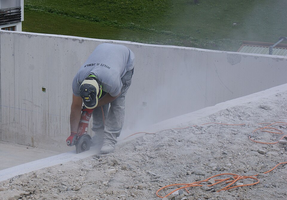
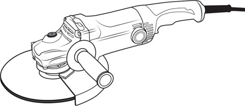
An angle grinder has a guard covering half the disk and it is held to the workpiece so that only the exposed portion of the disk makes contact with the workpiece.
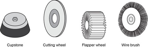
Disks other than for grinding are available for angle grinders (Figure 15). With these disks, the angle grinder becomes much more than a grinding tool. It is a very versatile and useful tool.
Cables
Current is conducted from the welding machine to the electrode and electrode holder by the electrode cable and from the workpiece to the welding machine by the ground or work cable. These cables are made from insulated copper or aluminum wire. Aluminum wire has the advantage of weighing less than copper and can dissipate heat more quickly, but it can carry only about 60% of the current load of copper wire.
The electrode cable is specially designed to enable the welder to move the electrode and holder without putting undue strain on the cable.
A typical electrode cable (Figure 16) consists of thousands of hair-like wires braided into strands. These strands are themselves braided to form the conductor and are enclosed in a durable paper wrapping that allows the conductor to move easily inside the insulation when it is bent. Outside the paper is a layer of rubber insulation surrounded by a layer of woven fabric reinforcement to provide additional wear resistance. The outer layer is special composition rubber with a smooth finish, highly resistant to wear.

The ground cable does not usually undergo as much movement as the electrode cable, so less flexible but equally wear-resistant cable is used.
Summary
As you prepare to weld, remember these main safety points:
- Always turn off your welding machine when it is not in use.
- Wear gloves when handling arc welding equipment.
- Keep all equipment dry and do not work in damp or wet conditions.
- Make sure that the workpiece or workbench is properly grounded.
- Do not overload the welding cables.
- Remove the electrode from the electrode holder before putting the holder down.
- Switch the welding machine off when your work is completed.
General Maintenance of Welding Machines
A welding machine must be maintained even when it is not in use. Make sure that equipment is stored where it will not be damaged when you are using other equipment. Protect portable welding machines from severe weather conditions.
Operate the machine as it was designed to be operated. When you use a machine, locate it so that it is well ventilated by cool, clean air. Keep it as far as possible from the dust of grinders and cutting machines. Keep it away from heaters and other heat-producing equipment and away from welding spatter. This will reduce the daily wear and tear.
Never use the current range or the polarity switch of a machine when there is a load on the circuit. Use these switches only when the machine is off or is idling before the arc is struck. Otherwise, the load may cause an arc in the switch and permanently damage the contacts.
Routine maintenance procedures that you can perform on welding machines include inspecting all cable connections to ensure that loose connections are not increasing wear on the equipment by adding to the circuit resistance. On portable fuel engine machines, check coolant levels and oil levels before each use.
Most AC-transformer-type welding machines have a forced air circulation cooling system powered by an electric motor connected to the primary circuit. As well as keeping the vent openings clear any time the machine is in operation so that the flow of air is unobstructed, remove the casing and thoroughly clean the passageways at least twice a year. In those units (such as motor-generator machines) that have air filters, inspect the filters regularly and clean them as required.
Storage
Store welding equipment in a dry location. Neatly roll cables in fairly large loops to reduce stress on the fibres and store them with like lengths so that they are easy to select for the job at hand.
 Self-Test B-6.3: Describe the Arc Welding Process and Equipment
Complete Self-Test 6.3 and check your answers.
If you are using a printed copy, please find Self-Test A-6.3 and Answer Key in the Appendix at the end. If you prefer, you can scan the QR code with your digital device to go directly to the interactive Self-Test.

References
BC Industry Training Authority. (2019). Piping trades apprenticeship program: Use Tools and Equipment—Level 1 harmonized [Binder]. Crown Publications, Queen’s Printer for British Columbia. https://www.crownpub.bc.ca/Product/Details/7960000261_S
Industry Training Authority. (2019). Piping trades apprenticeship program: Level 1—Competency B-5: Use welding equipment (Steamfitter). Crown Publications, Queen’s Printer for British Columbia.
Industry Training Authority. (2019). Piping trades apprenticeship program: Level 1—Competency B-5: Use cutting, brazing and soldering equipment (Plumber). Crown Publications, Queen’s Printer for British Columbia.
Industry Training Authority. (2019). Piping trades apprenticeship program: Level 1—Competency B-6: Use oxy-fuel cutting equipment (Plumber). Crown Publications, Queen’s Printer for British Columbia.
Industry Training Authority. (2019). Piping trades apprenticeship program: Level 1—Competency B-6: Use soldering and brazing equipment (Steamfitter). Crown Publications, Queen’s Printer for British Columbia.
Industry Training Authority. (2019). Piping trades apprenticeship program: Level 1—Competency B-7: Use oxy-fuel equipment (Steamfitter). Crown Publications, Queen’s Printer for British Columbia.
Industry Training Authority. (2019). Piping trades apprenticeship program: Level 1—Competency B-7: Use welding equipment (Plumber). Crown Publications, Queen’s Printer for British Columbia.
Media Attributions
All figures are sourced from Industry Training Authority (2019) and/or Camosun College (2019) and are used under the Creative Commons Attribution 4.0 (CC BY 4.0) licence unless otherwise noted. Images copyrighted by the BC Industry Training Authority are licensed under a Creative Commons Attribution-NonCommercial-ShareAlike 4.0 (CC BY-NC-SA 4.0) licence.
- Figure 1 Shielded metal arc welding Lincoln Excalibur 7018 1/8″ by Prowelder87 on Wikimedia Commons is used under a CC BY-SA 4.0 license.
- Figure 2 Gas pipeline welding, Azna 2017 by Hamid Soufi on Wikimedia Commons is used under a CC BY-SA 3.0 license.
- Figure 13 Faschina-concrete angle grinder-Betontrennschleifen-13ASD [Angle grinder on concrete], by Asurnipal on Wikimedia Commons is used under a CC BY-SA 4.0 license.
(Also commonly called stick welding or electric arc welding); A welding process that uses an electric arc between a coated electrode and the metal to join materials. (Section B-6.1)
The electrical pressure that pushes current through a circuit, measured in volts (V). (Section B-6.3)
The unit used to measure voltage, or the electrical pressure that pushes current through a circuit. (Section B-6.3)
The flow of electricity through a circuit, measured in amperes (A). (Section B-6.3)
The unit used to measure electric current, or how much electricity is flowing through a circuit. (Section B-6.3)
An electric current that changes direction back and forth many times per second. It is commonly used in homes and buildings. (Section B-6.3)
An electric current that flows in one direction only, from the negative to the positive side of a circuit. It is commonly produced by batteries and some welding machines. (Section B-6.3)
One complete change in an alternating current where the voltage goes from zero to maximum in one direction, back to zero, and then to maximum in the opposite direction. (Section B-6.3)
A smooth, wave-shaped pattern that shows how alternating current (AC) rises and falls over time as it changes direction. (Section B-6.3)
A type of alternating current that uses one electrical wave and is commonly used in homes and small buildings. (Section B-6.3)
A type of alternating current that uses three electrical waves working together to provide a steady and powerful supply of electricity, often used in industrial settings. (Section B-6.3)
A metal rod used in welding that carries electric current and melts to provide filler metal for the weld. (Section B-6.3)
The direction of electrical flow in a welding circuit, which affects how heat is distributed between the electrode and the workpiece. (Section B-6.3)
A welding setup where the electrode is connected to the negative side of the power source, causing more heat to be concentrated in the workpiece. (Section B-6.3)
A welding setup where the electrode is connected to the positive side of the power source, causing more heat to be concentrated in the electrode. (Section B-6.3)
A welding machine that has two controls—one for adjusting the main current level and another for making fine adjustments to voltage or arc characteristics. (Section B-6.3)
(job selector dial); A control on a welding machine used to set the main current level for a specific welding task. (Section B-6.3)
The voltage in a welding circuit when the machine is on, but the arc has not yet been started. (Section B-6.3)
The voltage present in a welding circuit after the arc is struck and the current is flowing. (Section B-6.3)
The metal that is melted and added during welding, forming the final weld as it cools and hardens. (Section B-6.3)
A coating on a welding electrode that helps protect the molten metal from air and keeps the arc stable during welding. (Section B-6.3)
Metal that is added during welding to help join two pieces together and form a strong weld. (Section B-6.3)
A condition where metal becomes hard and brittle, making it more likely to crack or break. (Section B-6.3)
Small holes or bubbles in a weld caused by trapped gas. (Section B-6.4)
A heated storage unit used to keep welding electrodes dry and at the correct temperature to prevent moisture from affecting weld quality. (Section B-6.3)
A type of strong metal alloy made mainly from nickel that resists heat and corrosion, often used in high-temperature or harsh environments. (Section B-6.3)
A metal alloy made mainly from nickel and copper that is strong and highly resistant to corrosion, especially in marine environments. (Section B-6.3)
A handheld device used in welding to hold the electrode and safely carry electric current to it during welding. (Section B-6.3)
A device used to attach the welding circuit to the workpiece or work surface, completing the electrical circuit and allowing current to flow safely. (Section B-6.3)
The short leftover pieces of welding electrodes that remain after most of the electrode has been used. (Section B-6.3)
A hard residue left on a weld after metal is melted and fused together. (Section B-1.1)
Power tools used to shape, smooth, or remove material from metal surfaces, often using a rotating abrasive wheel or disk. (Section B-6.3)
A type of grinder where the grinding wheel is in line with the motor shaft, used for precise work and hard-to-reach areas. (Section B-6.3)
Small, high-speed grinders used for detailed work, such as removing burrs, shaping metal, or working in tight spaces. (Section B-6.3)
Power tools with a rotating disk set at a right angle to the motor, used for cutting, grinding, and shaping metal and other materials. (Section B-6.3)