B-4.1 Describe the Principles of Lifting and Hoisting
Mechanical Advantage
The mechanical advantage (MA) of a mechanism is the factor by which input effort is multiplied to produce greater output force. Mechanical advantage describes how much a machine increases applied force. The mechanical advantage of a device can be used to determine how well it performs and whether it can perform a given job.
Most simple machines operate using the principle of MA, and it can be calculated using the following formulas.
- Levers: MA = length of effort arm ÷ length of resistance arm.
- Pulleys: All pulleys have a fixed MA, depending on the type. A single fixed pulley has an MA of 1:1. A single movable pulley has a MA of 2:1. A pulley with six ropes (block-and-tackle system) has an MA of 4:1.
- Wheel and Axle: MA = radius of wheel ÷ radius of axle
- Inclined Plane: MA = length of slope ÷ height of slope
Understanding mechanical advantage helps workers safely lift and move loads using rigging and hoisting equipment.
Pulleys
Single fixed pulleys can change the direction in which a force is applied and can transmit rotational motion into linear motion. However, they do not provide mechanical advantage, because the amount of force required is equal to the force of the load.
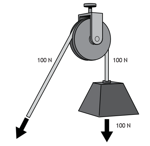
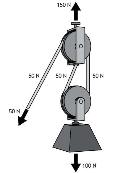
Movable and multiple pulleys can be used to provide significant mechanical advantage. In this case, there is a trade-off between force and distance: less force is required, but the distance required to do the work increases. (Note, the product of force × distance remains the same.) In Figure 2, although the effort is cut in half, the length of rope required will be twice the distance that the load travels.
Balance Points and Load Stability
Properly rigging a load of material (supporting or fastening it for lifting or transport) helps keep the load level and stable as it is lifted into the air by a crane or hoisting device. A poorly rigged load may shift and could cause the load to fall. To maintain stability, workers must consider the centre of gravity, sling locations, and sling types.
Centre of Gravity
The centre of gravity of an object is the point at which the object will balance, regardless of whether the object is upright, on its side, top, bottom, or end.
A suspended object will always move so that its centre of gravity is located directly below its point of support.
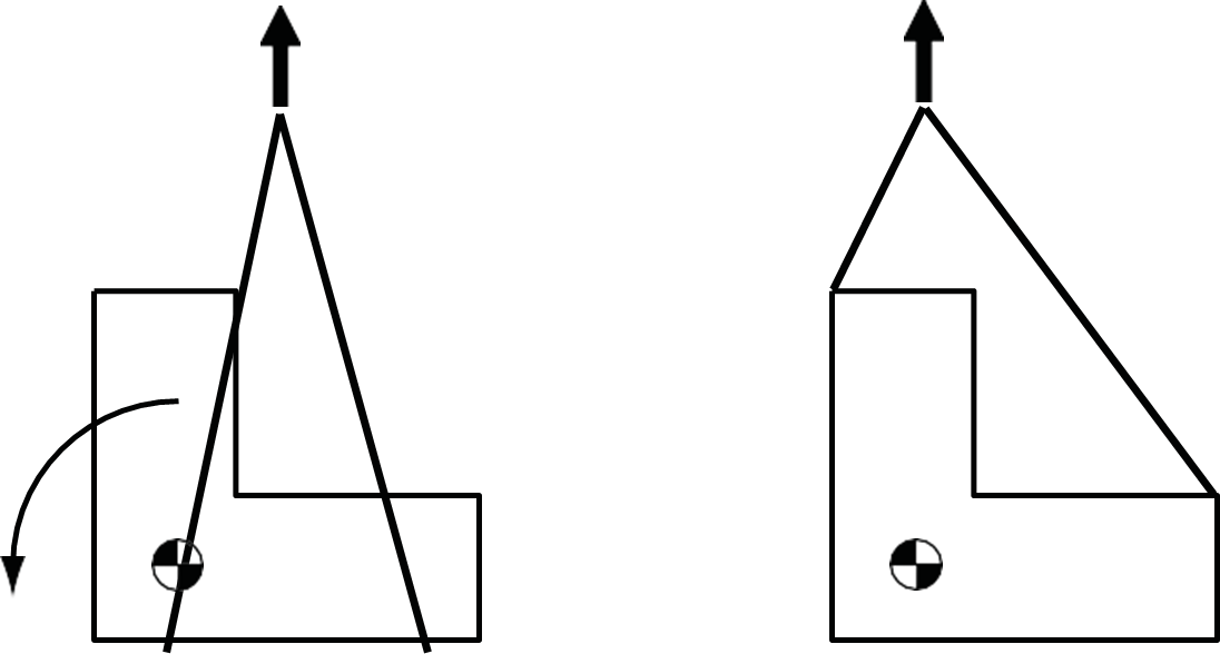
You must consider the location of the centre of gravity whenever you rig a load to be lifted by a crane. Estimate the location of the centre of gravity for the object to be lifted. Although the centre of gravity can be calculated using complex formulas, workers in the piping trades often determine it using careful judgment and short trial lifts. Complex or critical lifts should always be rigged by a competent, certified rigger. Use a sling arrangement that positions the lifting hook directly above the centre of gravity.

A load with the hook to the side of the centre of gravity will shift or tilt when lifted. This shift will continue until the centre of gravity rests directly below the hook.
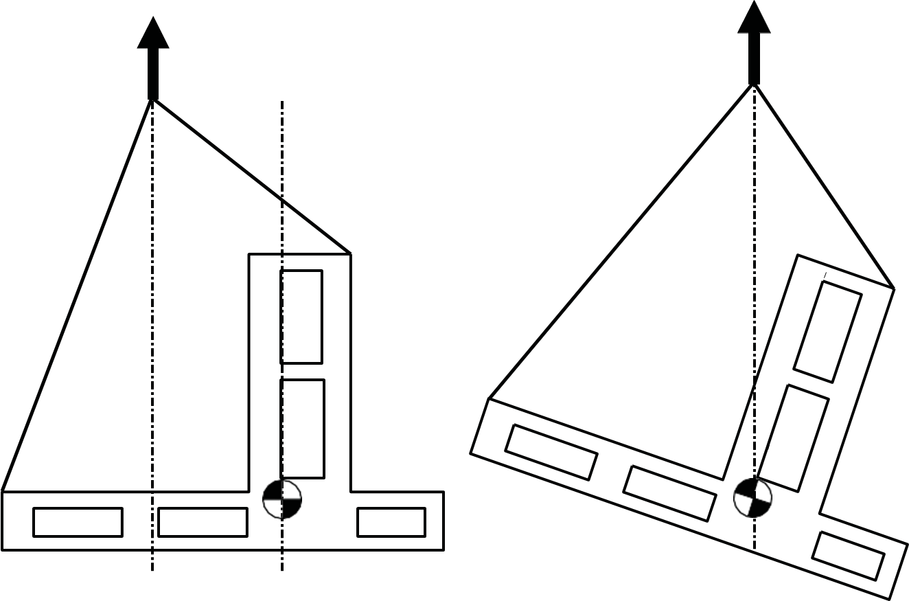

NEVER rig a load with the centre of gravity above the lifting point (or points). Doing so may cause the load to turn over. The natural position for the centre of gravity is below the point of attachment.
Sling Locations
The position of the sling attachment to the load is very important.
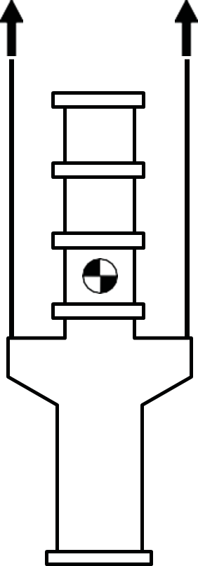
When using a sling, as shown here, ensure that the centre of gravity is located between the two slings. If the centre of gravity is beyond the slings, the load may topple over at the start of the lift. Rigging loads with their centre of gravity close to one sling is considered poor practice because of the increased risk of tipping. Always use a sling arrangement that places the centre of gravity below the sling’s point of attachment to the load.
When you are lifting loads with a crane, start the initial lift very slowly, and watch the load for signs of tilting or shifting. If the load tilts more than 5°, lower the load and rearrange the rigging.
Steps to a Safe Lift
Certification Requirements
The OHS Regulation Part 15: Rigging states that “Rigging and slinging work must be done by, or under the direct supervision of, qualified workers familiar with the rigging to be used and with the code of signals authorized by the Board for controlling hoisting operations.”
Training standards are often site-specific, where employers define what constitutes a qualified worker, with the OHS Regulation as the minimum requirement.
Labour organizations, private third-party training companies, and equipment manufacturers also offer training. The Canadian Standards Association Group (CSA Group) provides a rigging certification course developed with United Association Canada (UA) and the National Association of Union Schools and Colleges (NAUSC).
Lift Plan
A lift plan is a process that includes calculating load weight, identifying the lift-route, recognizing potential hazards (such as weather or overhead powerlines), selecting equipment and safety protocols, and establishing communication procedures. Lift plans can range from a quick, informal chat between a worker acting as a signal-person and a boom-truck operator to a formal process for a critical lift, requiring signed documentation from riggers, supervisors, engineers, and crane operators. This distinction between non-critical and critical lifts is often set by employers or crane companies.
Factors that may classify a lift as critical include:
- The proximity of the lift to power lines
- The need for two or more lifting devices
- Load weight exceeding 75% of the crane’s capacity
- Uneven ground or side loading on the crane
Calculations of Weight
Knowing the approximate weight of the load and rigging hardware is crucial for proper equipment selection. Load weights may be obtained from reliable sources such as shipping documents and forms, manufacturers’ specifications, or design plans (drawings). Weights of common material can be sourced from publications such as the IPT Pipe Trades Training Manual. Other scenarios may require calculations using standard weight of common material and applying the formulas for area and volume.
Equipment Selection
Approved hoisting equipment has a rated load called its rated capacity or working load limit (WLL). This indicates the maximum safe load the equipment can handle. This is based on the ratio of the ultimate breaking strength to the safety factor. Rigging load calculations are based on a design safety factor of 5:1 for material and 10:1 for critical or personnel lifts. This means that if a 1-inch wire rope has an ultimate breaking strength of 41,000 kg, with a safety factor of 5, the WLL would be 8,200 kg.
Communication
During a lift, the crane operator and signal person work together to execute the lift safely. Only an experienced, trained operator should control lifting equipment and ensure that movements are planned, slow, and thoughtful. Signal persons must know the proper hand signals or radio communication procedures and should have a pre-lift consultation with the operator to clarify the lift plan and communication. Clear communication is essential for safe lifting operations!
Load Security
Load integrity is considered if multiple objects are hoisted at once, as in the case of pipe bundles, or if a pick-and-carry operation is required. If the load consists of many like objects, use the proper sling arrangement for security or carry the load in a basket. During a pick-and-carry lift, the load is carried low to the ground and a snub line is used in addition to tag lines to control swing.
 Self-Test B-4.1: Describe the Principles of Lifting and Hoisting
Complete Self-Test 4.1 and check your answers.
If you are using a printed copy, please find Self-Test A-4.1 and Answer Key in the Appendix at the end. If you prefer, you can scan the QR code with your digital device to go directly to the interactive Self-Test.

References
BC Industry Training Authority. (2019). Piping trades apprenticeship program: Use Tools and Equipment—Level 1 harmonized [Binder]. Crown Publications, Queen’s Printer for British Columbia. https://www.crownpub.bc.ca/Product/Details/7960000261_S
Camosun College. (2019). Line C: Tools and Equipment—Competency C-3: Describe Rigging and Hoisting Equipment (Rev. ed.) [Learning guide]. BCcampus. https://collection.bccampus.ca/textbook/7c8Ymhnk/
Camosun College. (2015). Trades Access Common Core Competency C-3: Describe Rigging and Hoisting Equipment. Victoria, B.C.: Crown Publications. Download for free from the B.C. Open Textbook Collection (https://open.bccampus.ca/browse-ourcollection/find-open-textbooks/).
Lee, R. A. (2006). IPT’s pipe trades handbook and training manual (Rev. ed.). IPT Publishing & Training Ltd.
WorkSafeBC. (n.d.). Occupational health and safety regulation: Part 15—Rigging. https://www.worksafebc.com/en/law-policy/occupational-health-safety/searchable-ohs-regulation/ohs-regulation/part-15-rigging
Media Attributions
All figures are sourced from Industry Training Authority (2019) and/or Camosun College (2019) and are used under the Creative Commons Attribution 4.0 (CC BY 4.0) licence unless otherwise noted. Images copyrighted by the BC Industry Training Authority are licensed under a Creative Commons Attribution-NonCommercial-ShareAlike 4.0 (CC BY-NC-SA 4.0) licence.
How much a machine increases the force you put into it to make work easier. (Section B-4.1)
Basic devices, such as levers, pulleys, and inclined planes, that make work easier by changing the size or direction of a force. (Section B-4.1)
A wheel with a rope or cable that helps lift or move heavy loads. (Section B-4.1)
The equipment and methods used to attach and lift loads safely with cranes or hoists. (Section B-4.1)
A machine used to lift and move heavy loads using a hook, cable, and boom. (Section B-4.1, Section B-4.2)
A strong strap, rope, or chain used to lift heavy objects. (Section B-4.1)
The point in an object where its weight is balanced. (Section B-4.1)
A written or discussed plan that explains how a load will be safely lifted and moved. It includes details such as the weight of the load, the equipment being used, the lifting path, possible hazards, and how workers will communicate during the lift. (Section B-4.1)
(or rated capacity); The maximum weight a piece of lifting equipment can safely carry. (Section B-4.1)
A trained worker who gives hand signals or radio instructions to a crane operator during lifting operations. (Section B-4.1)
The condition in which a lifted load remains secure, stable, and properly contained so that individual items do not shift, separate, or fall during lifting, moving, or positioning operations. (Section B-4.1)
A lifting operation in which a crane or lifting machine raises a load and then moves it horizontally to another location while the load remains suspended, usually carried low to the ground for safety. (Section B-4.1)
A rope or line attached to a load to help control its movement and prevent it from swinging while it is being lifted or moved by a crane. (Section B-4.1)
A rope attached to a suspended load that workers hold to guide and steady the load, helping control its direction and rotation during lifting or positioning. (Section B-4.1)