B-2.1 Describe Portable Power Tools Used in the Pipe Trades
Portable power tools play a major role in virtually every trade. In the piping trades, you will be expected to be familiar with a wide range of portable power tools. You must be able to identify these tools, explain their uses, and select portable power tools appropriate for various processes. This section will explore tools that are powered by sources such as electricity, compressed air, and explosive charges.
Electric Portable Power Tools
Electric tools have seen much advancement in recent years, especially in the progress of battery technology. Lighter and more powerful than ever, almost any corded tool that is manufactured today is available in a cordless battery-powered design. Truly portable, cordless tools use a rechargeable battery cell that is composed of one of several different combinations of chemicals including nickel-cadmium, nickel-zinc, or lithium-ion.
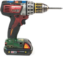
Corded, electrically grounded tools usually have a three-prong plug, with one prong serving as the ground pin. Double-insulated tools may have only two prongs.
Electric Saws
Portable electric saws are valued for the speed and efficiency with which they can do certain jobs. The circular saw, for example, is well suited for cutting cleanly into thick lumber and for trimming assembled work.
Portable Circular Saws
Portable circular saws can make straight cuts in a variety of materials and can also start cuts in the middle of a workpiece.
The size of the saw is identified by the diameter of the blade. As a rule, the larger the blade diameter, the more powerful the motor must be and the greater the depth of cut.
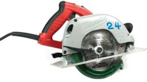
Portable circular saws can be used for both ripping and crosscutting. The depth of the cut is controlled by raising or lowering the base, and bevel cuts can be made by adjusting the tilt of the base.
The saw is usually guided freehand along a pencil or chalk line, so its accuracy depends on the operator’s guiding skill.
Straight cuts can be made using the rip guide, a standard attachment on most circular saws. Even greater accuracy can be achieved by securing a straightedge to the work and guiding the base of the saw along it during the cut.
Circular saws can also start cuts in the middle of a workpiece. This makes them useful for cutting rectangular openings in materials such as plywood, a task that is difficult to do with a handsaw.
Saw Blades for Circular Saws
Circular saws use three types of blades:
- Crosscut
- Ripsaw
- Combination
Use crosscut blades for crosscutting (perpendicular or against the grain) and ripsaw blades for ripping (parallel or with the grain). Use a combination saw if the work requires you to constantly change from crosscutting to ripping.
Tooth Characteristics
This illustration shows two saw-blade teeth. The four characteristics that distinguish one type from another are pitch, heel, hook, and gullet.
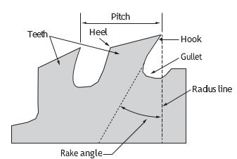
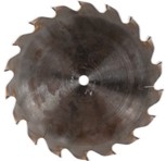
There are several designs of blades. Each blade design is intended for a specific cutting task and will last longer and perform better if used only for the intended task.
Rip blades are designed to cut solid lumber along the length of the stock. The teeth are square across their cutting edge and will cause chipping if used for cross cutting.
Crosscut blades have teeth sharpened to a knife-like point. They will produce a smooth, chip-free cut across the grain of solid lumber and they are ideal for cutting plywood regardless of the direction of the cut.
A standard combination blade provides an adequate cut with or across the grain of solid wood, as well as on various plywood’s and panel products. However, it does none of these cuts as well as blades specifically designed for each task.
The chisel combination blade is a popular blade for cutting solid lumber and plywood. The teeth are sharpened square across the front and on a bevel across the back, forming a slight point on the cutting edge. The blade is easily sharpened and, when sharp, cuts fast and produces edges smooth enough for most construction.
Non-ferrous metals can be cut with metal-cutting circular blades. The blade resembles a fine-toothed crosscut blade, but the teeth are square across the cutting edge like those of the ripsaw. These blades usually require lubrication on their sides to prevent the waste material from binding to the blade. The most common type of lubricant is a wax-stick which is rubbed on the sides of the blade.
Ferrous metals (metals that contain iron and form sparks when cut or ground) can be cut with an abrasive disk blade. This blade has no teeth and simply grinds a thin cut through the metal. The abrasive blade must be matched to the RPM of the saw and hardness of the steel being cut. Otherwise, the blade will either cut very slowly or wear out very quickly.
Masonry products are cut with an abrasive wheel similar to the type used for ferrous metals. Because masonry blades and ferrous cutting blades are similar in appearance, check to make sure you have the correct type of blade. Masonry blades will not cut metal, and metal cutting blades will not cut masonry.
Carbide-tipped blades remain sharp much longer than conventional steel blades. They can be used to cut wood, plastic and composition board as well as non-ferrous metals. The carbide tips, which are extremely hard and brittle, are brazed onto a standard-sized metal disk. The carbide tips are then ground to a shape suitable for the blade’s intended use. The shape of the tooth illustrated in Figure 12 is known as triple chip and can be used for plastic laminates, hardboard, plywood, aluminum, brass and for crosscutting lumber.
Carbide is so hard and brittle that it can be chipped and dulled through contact with other hard materials. As a result, all carbide-tipped blades require careful handling. You must not let the carbide come in contact with any hard surface, such as the metal parts of a saw, other saw blades, or concrete and masonry.
Sabre Saw (Jigsaw)
Sabre saws are used to make curved or irregular cuts in wood, plastics or metal.
The blade action is a high-speed up-and-down motion, with the cutting taking place during the up stroke.
The sabre saw is designed mainly for light cutting, but is also capable of making cuts through materials 40 mm to 50 mm (1[latex]\frac{1}{2}[/latex] in. to 2 in.) thick. The blade length should be such that when the blade is at the top end of its stroke, the lower end of the blade is below the bottom of the stock being cut.
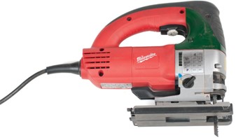
Although the sabre saw is capable of starting a cut in the middle of a piece of wood; it is much easier and safer to drill a starter hole through the workpiece and use the hole as the start of the cut. The rapid up-and-down action of the blade may cause the workpiece to chatter, so the workpiece must be secured and the sabre saw held firmly against the work.
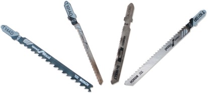
The most common types of sabre saw blades are shown in Figure 6. Note that there are two different end types, straight and hooked end. They cannot be interchanged.
The blades for plywood, particle board and plastics have fine teeth. The blade for cutting thicker plywood and lumber has coarse teeth.
The blade for cutting thin hardboard and plywood in a scroll pattern has fine teeth and is very narrow.
The blade used for cutting ferrous metals has very fine teeth set in a wavy pattern.
Reciprocating Saw
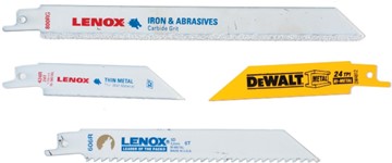
The reciprocating saw makes cuts in any direction. It can do heavier work than the sabre saw. This type of saw can be used to cut metal, wood, fibreglass and virtually any other substance, using the correct blade.
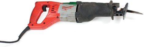
A reciprocating saw is a type of saw in which the cutting action is achieved through a push-and- pull (hence reciprocating) motion of the blade.
This type of saw, also known simply as a recip saw or Sawzall (a trademark of the Milwaukee Electric Tool Company) has a large blade resembling that of a jigsaw and a handle oriented to allow the saw to be used comfortably on both vertical and horizontal surfaces. The typical style of this saw has a shoe or foot plate at the base of the blade, similar to a sabre saw. The user rests this foot against the surface being cut to counter the tendency of the blade to push away from or pull towards the cut as the blade travels through its cycle.
Indispensable in construction, demolition and service work, most of these tools have a quick- release blade function that allow speedy blade replacement without the use of additional tools.
Power Cut-off Saw (Chop Saw)
A power cut-off saw is used to cut sections of lightweight material to length. Power cut-off saws use a thin, abrasive, circular disk as a saw blade. The disk is made from mineral or synthetic grains that are fibre-reinforced and resin-bonded. This disk comes in thickness from 2 mm to 3 mm ([latex]\frac{1}{16}[/latex] in. to [latex]\frac{1}{8}[/latex] in.) and in diameters from 150 mm to 500 mm (6 in. to 20 in.).
The saw in Figure 9 is called a chop or cut-off saw. The chop saw has the mandrel and motor mounted on a pivoting frame. You operate it by grasping the handle fastened to the pivoting frame and lowering the rotating cut-off wheel into the workpiece. The workpiece is secured on the bed of the tool by built-in vise or clamp. Power cut-off saws are also manufactured with special features for a variety of applications.
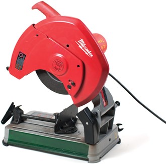
This saw cuts relatively quickly, but produces a considerable amount of heat at the site of the cut, which may damage the workpiece. It is used to cut steel that will not suffer too much from heat build-up.
Abrasive Cut-off Wheels
Abrasive cut-off wheels are designed for cutting masonry products or metal.
Metal-cutting wheels are available in two grades, fast-cut or long-life. Fast-cut wheels cut faster but wear out sooner than long-life wheels. Most metal-cutting abrasive wheels will cut steel, stainless steel, cast iron and aluminum.
Each abrasive cut-off wheel has a maximum speed listed in RPM (revolutions per minute). You must make sure that the rated speed of the cut-off wheel is greater than the speed of the motor, or the wheel will break apart and could possibly injure you or a workmate. Sparks and dust that are created can be a serious hazard to your eyes and lungs. Take extra precaution when operating this tool.
Portable Band Saw
Portable band saws are available in a variety of models and sizes.
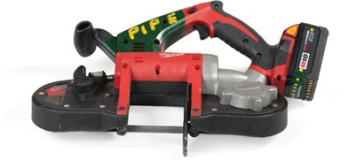
The size of the metal-cutting band saw is designated by the thickness of stock you are able to cut with it. Standard sizes are 115 mm, 180 mm and 255 mm (4[latex]\frac{1}{2}[/latex] in., 7 in. and 10 in.). Some larger models are capable of cutting through a pipe that is 50 cm (20 in.) in diameter. The material being cut is typically held in a portable vise.
Metal Cutting Blades
Metal-cutting band saw blades are defined by their grades of steel, tooth formation, tooth set and blade width.
Grades of steel include:
- Carbon steel
- Semi-high-speed steel
- High-speed steel
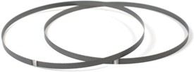
Figure 11 Band saw blades (BC Industry Training Authority, 2019). CC BY-NC-SA 4.0
Carbon steel blades are used for general purpose cutting on a standard band saw. Blades made of carbon steel are the least expensive of the three types, but are less durable than the other grades.
Semi-high-speed steel blades cut 50% faster than carbon steel blades. They are harder than carbon steel, but are able to withstand mechanical shocks and vibrations that would break harder, more brittle blades.
High-speed steel blades cut better and last longer than other blades, but are more expensive and more delicate than the other two grades.
Tooth Formations
Tooth formations include:
- Regular
- Hook
- Skip
Band saw blades with regular teeth are used for straight and curved cuts in most ferrous and hard non-ferrous metals. Blades with regular teeth can be considered general-purpose blades.

The hook-tooth blade is best for fast cutting of non-ferrous metals. The large rounded gullets are capable of fast chip removal and the forward slope of the tooth requires less downward pressure to cut. Thin sections of metal should not be cut with this tooth style due to the wide spacing of the teeth.

The skip-tooth blade is very similar to the hook tooth. Unlike the hook tooth, which can only cut softer metals, the skip tooth is capable of cutting ferrous metals. The wide spacing of the skip tooth makes the blade suitable for fast cutting of large sections of steel.

Hook and skip-tooth types are available in 3 to 6 teeth per inch. Regular-tooth styles range from 6 to 32 teeth per inch. The number of teeth per inch affects the cutting speed of a band saw, and the size of stock it is best suited to cut. Blades with large numbers of teeth per inch are able to cut small, thin pieces of metal but are slow for cutting large sections. Blades with few teeth per inch cut faster but are too coarse for cutting thin sections of metal. Too many teeth in the cut will result in destruction of the teeth.
Tooth Set
Set is defined as the left-and-right positioning of the teeth to provide a wider cut than the thickness of the blade (this creates the kerf). The wide cut provides clearance for the blade within the cut, preventing binding and overheating.
There are two types of tooth sets available on metal-cutting band saws, Raker and Wavy set.
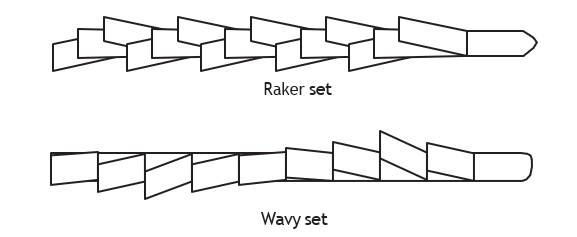
Hook- and skip-tooth blades have raker set teeth. Regular-tooth blades with up to 24 teeth per inch come with either raker set or wavy set teeth. All regular-tooth blades with more than 24 teeth per inch have wavy set teeth.
Blade Width
Band saw blades are available in widths ranging from [latex]\frac{1}{4}[/latex] in. to 1[latex]\frac{1}{4}[/latex] in. The narrower blades are able to cut curves of a smaller radius than are the wider blades. Wide blades used for straight cuts.
Portable Hand Drills
The portable electric hand drill can be used for a variety of tasks, including drilling holes, driving screws and mixing concrete. Cord-supplied drills may be double-insulated or of the three-prong type. Always make sure that you identify the type.
Most electric hand drills are manufactured with a pistol grip. A trigger switch is located on the pistol grip to allow for single-handed use during light-duty operations.
Heavy-duty portable hand drills incorporate removable side- and rear-mounted handles for extra control during two-handed operation.
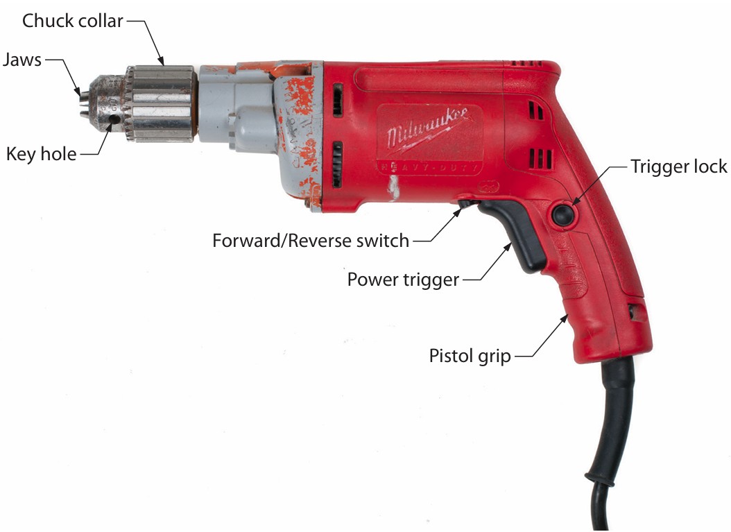
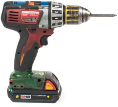
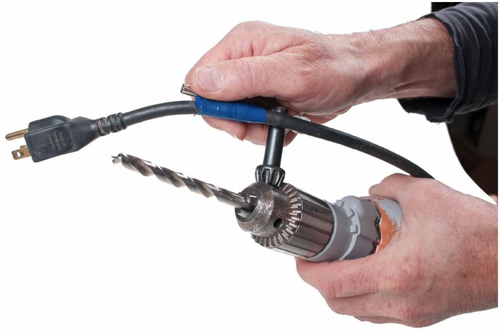
The drill bit is secured to the portable power drill by means of a chuck. The conventional style is a three-jawed chuck. that can be opened and closed by rotating the knurled outer sleeve, but final tightening is done with a special wrench known as a “chuck key” (Figure 17). The chuck key is inserted into a hole on the chuck so that the teeth on the key engage matching teeth on the chuck sleeve. Final tightening with the chuck key should be performed at two points on the three-jawed chuck to ensure a tight contact.
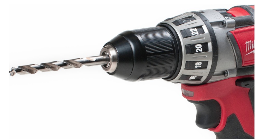
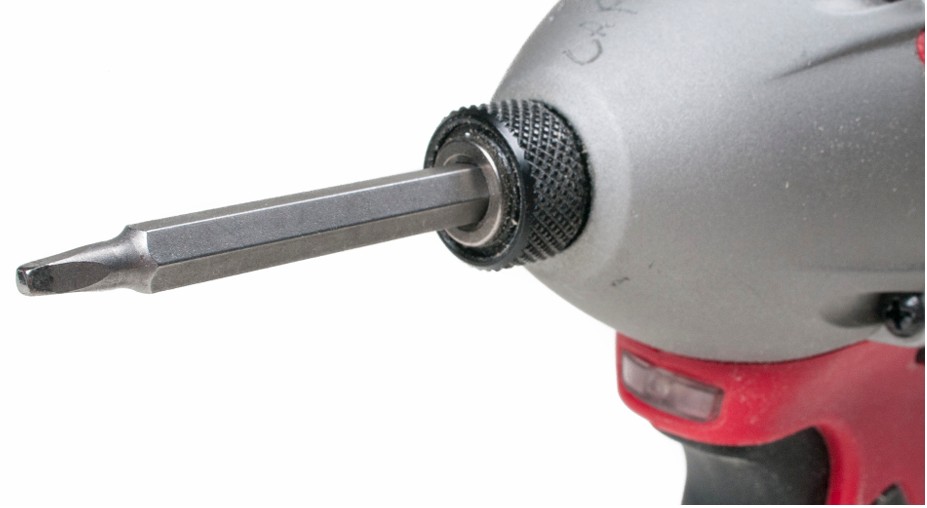
Another style of chuck is the quick-release hex chuck (Figure 19), originally designed to hold screwdriver bits but that also fits many drill bits that have hex shanks with a retaining channel.
Control Switches
Some portable electric drills only have an on-off switch. This type of switch limits the use of the electric drill to those operations that require a clockwise rotation of the chuck at the fixed speed at which that particular drill turns.
Other drills are manufactured with a variable speed switch. These switches provide control over the chuck speed in relation to the travel of the control switch. This control allows the electric drill to be used for a variety of tasks.
Driving screws and drilling soft materials require a slow-turning drill, while other operations, such as drilling hard materials, require higher speeds.
An additional switch found on some drills allows the motor to turn counter-clockwise (“reverse”) as well as clockwise (“forward”). When both a variable speed switch and a reversible switch are present on an electric drill, the drill can be used to remove screws as well as to drive them.
[latex]\frac{1}{4}[/latex] Inch Drill Motors
Most [latex]\frac{1}{4}[/latex] in. drill motors are used for light-duty drilling operations. The [latex]\frac{1}{4}[/latex] in. means that the drill will accept a maximum [latex]\frac{1}{4}[/latex] in. shank size. The chuck on a [latex]\frac{1}{4}[/latex] in. drill motor turns about 1500 to 1800 RPM. Such high speeds are good for drilling small holes in soft metals but tend to burn drill bits if used for hard metals. The [latex]\frac{1}{4}[/latex] in. drill does not produce enough torque (turning power) at low speeds for driving screws.
[latex]\frac{3}{8}[/latex] Inch Drills
These drills can turn at a much slower speed than a [latex]\frac{1}{4}[/latex] in. drill. Average chuck speed is 750 to 900 RPM for [latex]\frac{3}{8}[/latex] in. drills. Considerably more torque is generated, making the [latex]\frac{3}{8}[/latex] in. drill more suitable for drilling larger holes in metal. A [latex]\frac{3}{8}[/latex] in. drill is often equipped with a forward-reverse switch and a variable speed switch.
[latex]\frac{1}{2}[/latex] Inch Drills
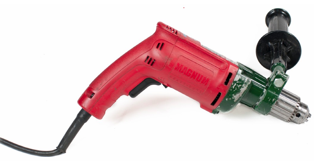
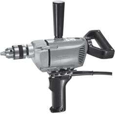
These drills generate substantial torque and are usually equipped with an additional handle to provide the operator with added leverage. Heavy-duty models have a pistol grip on one side, a removable T-handle opposite the pistol grip, and a D-handle at the back (Figure 20).
Drill Bits (Twist Drills)
Twist drills are also commonly called drill bits. Twist drills may be made from carbon steel or high- speed steel. High-speed steel drills are harder and can drill harder metals. High-speed steel remains sharp longer than carbon steel and is able to withstand higher temperatures.

Drill Sizes
Twist drills are available in sizes designated by one of four different systems:
- Metric
- Number
- Letter
- Fractional
Metric
Twist drills in metric sizes are usually supplied in 0.5 mm increments. However, they can be purchased in increments of 0.1 mm. Metric twist drills are commonly available in sizes from 0.5 mm to 15.5 mm in diameter.
Number
Twist drills in the number system range from 0.0135 in. to 0.228 in. in diameter. Size #80 is the smallest (just under [latex]\frac{1}{64}[/latex] in. in diameter) and size #1 the biggest (just less than [latex]\frac{1}{4}[/latex] in. in diameter). These sizes are commonly used in the gas fitter trade and are referred to as orifice drills.
Letter
Letter sizes range from A to Z, and are a continuation of sizes larger than number size #1. Size A is equal to 0.2344 in. in diameter and size Z is equal to 0.413 in. in diameter.
Fractional
Fractional bit sizing is very common in the construction and service trades. Fractional sizes start at [latex]\frac{1}{64}[/latex] in. in diameter and increase in size by 64ths up to 1 in. Larger bits are available in fractional sizes at varying increments of [latex]\frac{1}{32}[/latex] in., [latex]\frac{1}{16}[/latex] in. and [latex]\frac{1}{8}[/latex] in.
By intermixing fractional, number and letter sizes you can get up to 138 different sizes less than [latex]\frac{1}{2}[/latex] in. in diameter. Larger drills (over [latex]\frac{1}{2}[/latex] in.) are available with reduced shank sizes so that they can be used in standard chucks.
Spade Bits
The spade bit shown below is designed to drill into wood products only. Spade bit sizes range from 9 mm ([latex]\frac{3}{8}[/latex] in.) to 38 mm (1[latex]\frac{1}{2}[/latex] in.) diameter.

The quality of the cut produced by the spade bit is not as good as most other bits. Therefore, its use is limited to rough work.
Self-Feeding Multi-Spur Bits
This self-feeding multi-spur bit uses the screw point to pull the bit through the wood while the sides of the bit guide it. Having a very short centre point, the multi-spur bit drills virtually flat-bottomed holes.
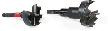
Multi-spur bits are available in sizes from 25 mm (1 in.) to 75 mm (3 in.). Their cutting action cuts clean, but shallow holes. Many have replaceable screw points.
Self-Feeding Auger Bits
Auger bits drill clean, accurate, straight and deep holes through wood. The bit is guided by both the screw point of the bit and the sides of the hole. Waste from the hole is carried to the surface by the spiral flutes.

Countersink Bits
When flathead screws are to be installed flush or below the surface of a wood workpiece, the countersink bit will drill a broad shallow hole to receive the head of the screw.
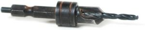
Countersink bits may be used before or after the pilot hole for the screw shank and threaded portion has been drilled.
Carbide-Tipped Bits
Carbide-tipped drill bits are used to drill holes in hard, abrasive materials such as concrete, stone, masonry, brick and ceramic tile.

Drilling into these materials requires a slow-turning drill (350–500 RPM) to prevent the bit from overheating. Special hammer/percussion drills can be used when multiple holes in masonry are to be formed.
Hole Saws
The hole saw is designed to cut large diameter holes in wood or sheet metal. The hole saw has an arbour bit (pilot bit) at its centre that enters the workpiece before the hole saw and serves to guide the hole saw as it enters the material.
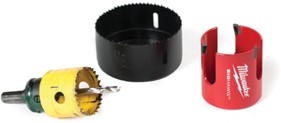
Hole saws are available in sizes from 14 mm ([latex]\frac{9}{16}[/latex] in.) to 111 mm (4[latex]\frac{3}{8}[/latex] in.) in diameter. The depth of the hole drilled is restricted by the length of the hole saw. Standard lengths are 12 mm ([latex]\frac{1}{2}[/latex] in.) or 28 mm (1[latex]\frac{1}{8}[/latex] in.).
Hammer Drill (Roto-Hammer)
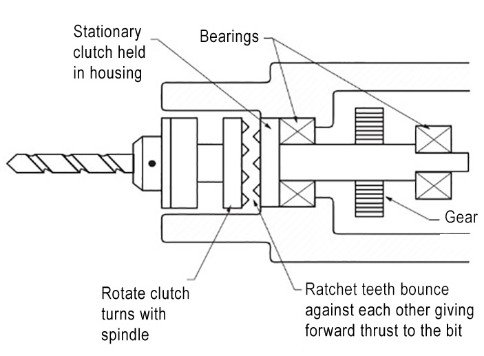
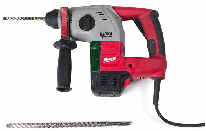
A hammer drill, with heavy duty versions known as a rotary hammer or roto-hammer, is a rotary drill with a hammering action. The hammering action provides a short, rapid force to pulverize brittle material and provide quicker drilling with less effort. Many types allow the hammer and rotation functions to be used separately or in combination (hammer mode, drill mode, or both). When used in the hammer mode, the tool provides a function similar to a jackhammer for light chipping work.
Hammer drills are well suited for drilling holes in masonry or stone. They are also used to drill holes in concrete footings or slabs for supporting and installing piping. The hammering action helps to break up the masonry so that it can be removed by the drill bit’s flutes.
Demolition Hammer (Chipping Gun)
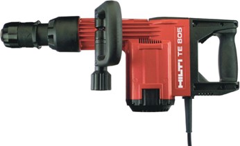
Demolition Hammers are larger and more powerful than roto-hammers and operate in hammer mode only, often earning them the name as a “chipping gun or jack hammer.” It is used for removing or demolishing concrete and masonry work.
Angle Drill Motor
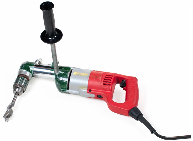
Drilling straight holes in tight spaces requires the use of a specialized type of drill motor. Angle drills have their chuck mounted at right angles to the drive motor, allowing for the motor to remain horizontal when drilling vertical holes (and vice-versa). Multi-positional handle attachments help maintain control in close quarters.
Some manufacturers produce high-torque, high-powered angle drills that are specifically designed for cutting holes in wooden studs and joists for running pipe work. Known by names like Hole-Hawg, they offer impressive force that can handle self-feeding bits in excess of 4[latex]\frac{1}{2}[/latex] in. in diameter.
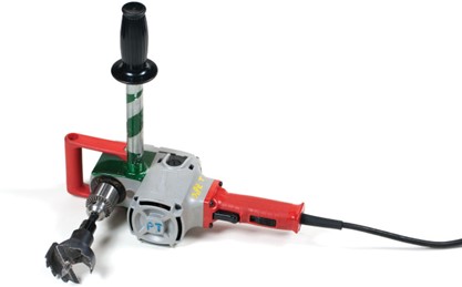
Always ensure that concealed objects such as nails and wiring have been located prior to drilling and maintain good balance during operation at all times.

Safety is paramount when using this tool because it generates substantial torque.
Pipe Saddle Drill
This specialized tool provides a slip-resistant platform to be used when drilling a pipe saddle (mechanical type of branch outlet). It allows for the drill motor to be centred on the convex pipe surface with adjustable straps and tensioning ratchets. Some varieties of pipe saddle drills allow for “hot tapping” into a live pipe so that the piping system need not be shut down and drained.
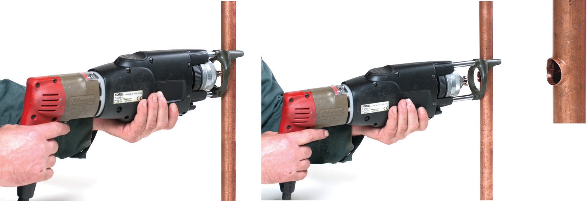
Extracted-Tee Drill
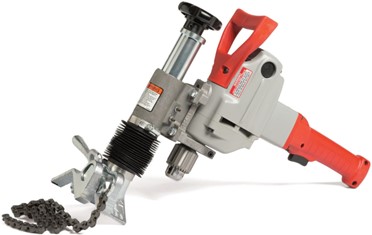
Tees can be extracted in the walls of some types of copper tube using a tool specially designed for this purpose. The drill’s head does the unique job of both drilling and forming the branch outlet. The extracted outlet must be brazed because it is very shallow compared to a standard branch tee fitting, but the resulting formation is quite strong.
Coring Machine
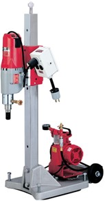
Coring machines (also called core drills) are designed for producing horizontal or vertical round holes in masonry. Designed much like a drill press for concrete and brick, they have hollow steel cylindrical bits that create a long core (tubular sample) of the material. Commonly, the resulting penetration is used for the installation of pipe work in new construction, renovation or piping relocation work.
The bits used for coring machines are essentially diamond-tipped hole saws, minus the presence of an arbour bit. Water is fed to the bit through a direct hose connection, or by means of a portable tank to aid in the cooling of the bit and to remove slurry (mixture of concrete and water) from the kerf of the cut.
Coring machines must be securely fastened to the work surface by means of concrete anchors or the use of a brace to tension the stand of the machine firmly. Suction-type bases have been developed for quicker mounting without damage to the wall or floor finish.
Angle Grinders
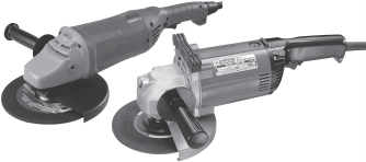
Angle grinders may be used for removing excess material or for cutting material. There are many different kinds of disks that are used for various materials and tasks, such as cut-off disks, abrasive grinding disks, honing (abrasive) stones, sanding disks, wire brush wheels and polishing pads.
The angle grinder has large bearings to counter side forces generated during cutting. It is sometimes referred to as a side grinder).
The motor drives a geared head at a right angle on which is mounted an abrasive disk that can be replaced when worn. Angle grinders typically have an adjustable guard and a side-mounted handle for two-handed operation. Light and powerful, they are essential for pipe fabrication work.
Grinding Wheels and Disks
A grinding wheel or disk is a shaping or cutting tool made from natural or artificial abrasive particles. The wheels are made in numerous shapes and sizes. A small amount of stock is removed by each abrasive particle as it passes over the work. Grinding wheels are used for rough grinding, smooth finishing, and cutting or removing metal or other materials.
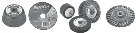
The most widely used abrasives in grinding wheel and disk construction are silicon carbide and aluminum oxide. Wheels containing particles of diamonds, either artificial or natural, are also made for limited special purpose application. The wheels and disks you encounter will usually be made of aluminum oxide.
The abrasive grain size determines the coarseness or fineness of the grinding wheel. The grain size is determined by the smallest screen mesh through which they can pass. For example, if the smallest screen through which the grains pass has 100 openings per inch, the grain size is known as 100 grit, with each grain approximately [latex]\frac{1}{100}[/latex] in. Grinding wheel abrasive grits from 6 to 24 are considered coarse, grits from 30 to 60 are medium, grits between 70 and 100 are fine and those over 100 are known as extra-fine.
One function of any bonding material is to hold each abrasive particle intact as long as it is sharp. When the particles become dull, they dislodge and expose other particles with sharp edges.
The hardness (grade) of a grinding wheel or disk refers to the strength with which the bond holds the abrasive particles together in the wheel, not the hardness of the abrasive particles.
The structure of a grinding wheel indicates how far apart the grains are spaced (grain density). If the spacing of the grains is close, the structure is dense. If the spacing is relatively wide, the structure is open. Grinding wheel structures are rated by numbers.
An open-structure coarse-grain wheel (which provides better chip clearance) is used on soft materials. Dense-structure fine-grain wheels are used where a smooth surface finish is required. Do not use wheels with a dense structure if the work material tends to clog the grinding wheel face.
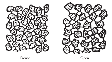
Choose a wheel or disk structure by compromising between the desired finish and the material removal rate. Always select a grinding wheel with a rated RPM at least as high as the grinder spindle no-load speed.
Allowing the wheel to operate at or slightly below the maximum safe speed automatically determines the cutting speed preferred for that wheel when used against material for which it was designed.
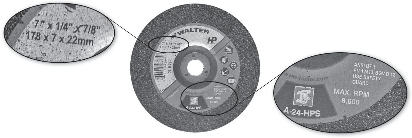
Markings
The standard marking system for most grinding wheels indicates:
- The maximum permitted operating speed (in RPM or m/sec)
- The wheel diameter
- The wheel thickness
- The hole diameter
- The grit size
Portable Electric Pipe Fabrication Tools
There are many portable electric tools designed for on-site pipe fabrication.
Portable Power Drives
The portable power drive is usually used with a tri-stand vise for pipe support. Weighing as much as 25 lbs., it is a powerful but compact drive for turning a drop head threader or a large-geared threader. When used with the geared threader, the drive is mounted on the threader by using an adapter.
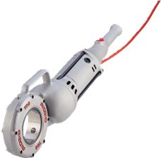
When a drop head threader is used, a support arm must be locked on the pipe if the pipe size is 1 in. or larger. In conjunction with the support arm, this drive can be used to turn drop head die threaders, with or without the use of a tri-stand supporting vise.
The maximum pipe capacity for most power drives is 2 in. pipe with a drop head threader and 6 in. pipe when using the geared threader.
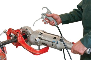
In addition to threading uses, some portable power drives will also power hoists and winches and other accessories and operate large valves. It is activated by a switch button on the handle.
Power Pipe Cutter
The portable power drive can be used to operate a heavy duty displacement cutter that can provide square cuts on pipe up to 12 in. NPS with wall thickness up to schedule 40. A hydraulic foot pedal provides the required force to feed the wheel through the pipe wall while the cut is achieved without dust or sparks.
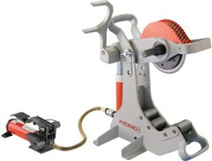
A pipe roller is available for this tool that allows it to be used to rotate a pipe while a worker bevels one end for welding preparation.
Copper Cutting and Preparation Machine
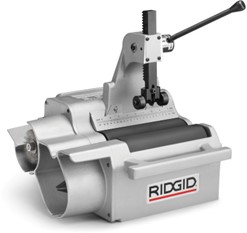
The copper cutting and preparation tool is useful for cutting, reaming, de-burring and cleaning copper pipe and fittings up to 4 in. It is suitable when multiple cuts are to be made for numerous fit-ups.
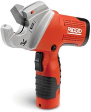
Plastic Pipe and Tubing Power Cutter
These types of powered cutters are designed to make precise cuts in multiple types of plastic materials. They are battery powered and suitable for use on polyethylene (PE), polypropylene (PP), PEX, rubber hose, PVC and CPVC, with a capacity typically up to 2 in.
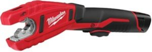
Copper Tubing Power Cutter
This cordless tool can save time when making numerous cuts on copper tubing. Weighing typically less than 10 lbs., it can self-adjust for tubing sizes between [latex]\frac{3}{8}[/latex] in.–1 in. OD tube and has a compact head suitable when cutting in tight spaces.
Power PEX Expansion Tools
Due to the memory capability of certain types of PEX, one method of joining the tubing is by expansion of the tube and a special PEX ring. Power tubing expanders are most commonly of the cordless electric type and have the added advantage of one-handed operation with heads that often have an auto-rotate feature.
Power Press Tool
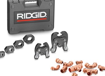
A fast one-time connection for copper, stainless steel and even PEX tubing is the use of press-fitting technology. This is popular due to its speed of installation and the fact that no flame or heat is required for copper connections. The barrel on the head can often swivel to obtain multiple installation positions.
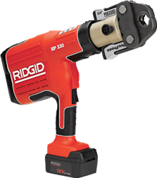
Additionally, for tubing sizes over 2 in., press-rings are available that fit around larger fittings, typically up to 4 in. A special actuator-jaw attachment is used to press the ring while it remains around the fitting until the jointing process is complete. The jaws allow for a 180° swivel feature that permits the tool to connect to the ring at any angle relative to the tubing, allowing greater access in tight spaces. Note that the pressing action of the tool cannot be stopped once activated, so the operator must make sure that fingers are kept well away from pinch points.
Electric Soldering Tools
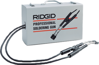
Professional electric soldering tools (guns) are intended for rapid, flameless soldering of copper tubing up to approximately 3 in. in diameter. Specially designed for renovation and repair work, they often utilize long cables to aid in accessing the work.
Fusion
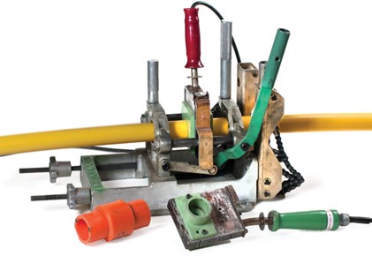
Fusion is a heat process that is used to join two pieces of thermoplastic pipe (pipe that is capable of being re-melted and re-molded). Pipe fusion involves using a tool that will melt two ends of the pipe to be welded and some method that will apply force to their surfaces until set. The two pieces then cool together and form a permanent bond. Generally, polyolefins (such as polypropylene and polyethylene plastic) are used for this application. (Polyolefins do not join by solvent cementing because they have excellent chemical resistance.)
Portable Power Tubing Bender
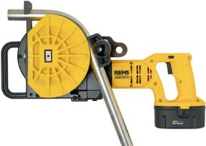
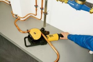
Most of these powered benders have radius abilities of 180° and offer a selection of bending formers for different diameters of copper tubes, aluminum and soft steel tubing, and pneumatic and hydraulic tubing. Most come with features that allow for bench mounting of the bender for multiple bending at the job site. Maximum capacity for these models is usually 1[latex]\frac{1}{8}[/latex] in. OD.
Portable Piping Maintenance Tools
There are many portable electric tools designed for on-site piping maintenance.
Power Drain Cleaning Tools
Drain cleaning tools are used to unblock clogged or obstructed drainage and venting pipes. Most types use some form of rotating auger that moves down the pipe to break up or retrieve the obstruction, while other varieties of machines may use jetted water to blast through material.
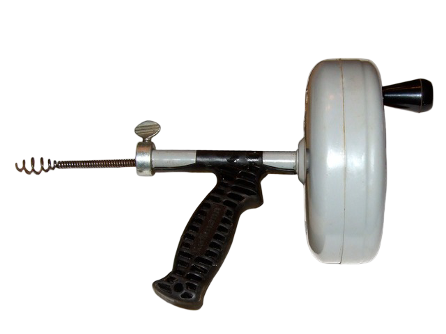
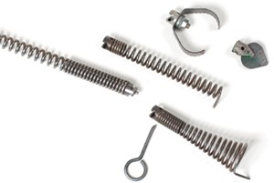
A drain auger is also known as a snake and consists of a coiled metal wire often wrapped around a wire core. Augers work to clear drains in one of several ways:
- The end of the auger’s wire digs itself into the obstruction much like a corkscrew, allowing retrieval of the object (hair, cloth, etc.).
- The end of the auger breaks up the object, allowing it to pass through the drain (tree roots, paper, etc.).
- The snake scours around the inside surface of the pipe, scraping off accumulated matter (ranging from mineral deposits to bacon fat) that was reducing the effective inside diameter of the drain.
Sink Machines
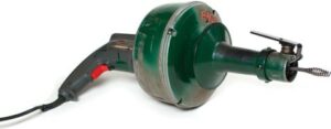
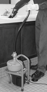
Typically using an auger that is approximately [latex]\frac{5}{16}[/latex] in. in diameter, sink machines are light-duty drain cleaners that are for drains sized 2 in. or less, such as kitchen sink, lavatory and shower drains. They are often powered by pistol-grip-style drill motors or small motors that are meant to be positioned on the counter top, or near the point of use.
Drum Machines
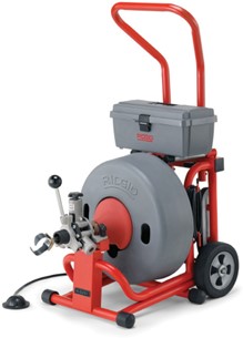
These larger capacity drum machines have the ability to vary the speed of the cable feed and rotation. Using [latex]\frac{3}{8}[/latex] in. or [latex]\frac{1}{2}[/latex] in. cables, they are capable of cleaning drain lines in excess of 4 in. Larger machines can be equipped with 100 ft cables of either [latex]\frac{3}{4}[/latex] in. or [latex]\frac{5}{8}[/latex] in. diameter that can clean drains as large as 10 in. In drum-style drain cleaning machines, a pneumatic foot switch is commonly incorporated as a safety feature. The switch uses air pressure—rather than electricity—to control the motor. This design eliminates the risk of electrical shock, especially in wet or damp environments where water contact is likely.
Sectional Drain Cleaning Machines
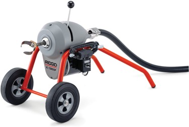
Sectional drain cleaning machines allow the drain auger to be added in sections instead of being self-contained in a drum. Often, more than one size auger can be driven with the same motor. One characteristic of this style of drain machine is that it can offer the operator more control of the auger through the manipulation of the control handle.
Water Jetters
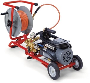
Water jetters propel flexible lines through sludge, soap and grease blockages. As it is pulled back, it power-scrubs the line, flushing away debris. Most operate with over 2000 psi water pressure to provide the required cleaning power to do the job.
Pipe Inspection Cameras and Locators
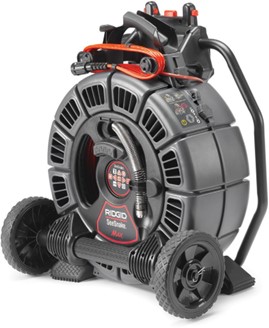
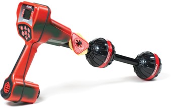
Pipe inspection cameras can visually show the nature or severity of obstructions or failures of piping systems. Especially valuable when inspecting underground services, pipe inspection cameras can record filmed data with the on-board hard drive, and some models make instant digital copies as well. LCD displays record the distance to the camera head to aid in locating the problem, while some cameras can transmit a signal to be detected with pinpoint accuracy with the aid of a locator device.
Pipe Freeze Kits
Pipe freeze kits stop the flow of water while a system is inspected or repaired. Once the system maintenance is complete, the “ice plugs” are slowly melted and the system is put back in service.
There are electric versions of these systems (as shown), but many use bottles of refrigerant gases to perform the same task with a similar result.

Pneumatic Portable Power Tools
Air tools are often used to do work in explosive or flammable atmospheres, such as in grain elevators or other places where sparking from inside an electric tool could cause a fire or explosion.
Safety with Air Tools
Using tools powered by high-pressure air can be very hazardous. In addition to the hazards of flying materials, there are many other dangers.
- Air tools are very noisy. Hearing damage can result unless proper ear protection is worn. This protection must be worn at all times, not only by the operator but by other persons nearby.
- Continuous vibration can cause damage to nerves. Use heavy gloves if you do a lot of impact work.
- Fittings often come loose from their retainers and can fly a considerable distance at high speed. When using air tools, be cautious of where you point the tool.
- High-pressure air is a severe hazard. Never expose yourself or your fellow workers to any direct blast of air as they can drive particles under your skin or inject air bubbles onto your bloodstream. Never use compressed air to clean your clothing because particles can be blown into your skin.
- Blowing air at your clothing could also react with some petroleum products and cause combustion.
Never use air tools in an area where the exhaust from the tool could stir up clouds of toxic chemicals or hazardous materials such as asbestos dust.
Air Supply for Air-Operated Tools
Air or pneumatic tools are operated by compressed air supplied by an air compressor. This compressor is pre-set to maintain a constant supply of compressed air at pressures ranging between 350 kPa (50 psi) and 1050 kPa (152 psi). A reservoir tank attached to the compressor retains a supply of compressed air to assure sufficient volume.
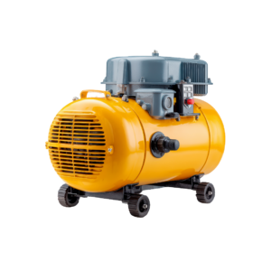
Compressed air may also be found piped to quick-connectors placed conveniently around the shop. High- pressure flexible rubber air hoses are used to connect the air-operated tool to the wall outlet. These hoses must be kept in good condition, and their end connections must be tight. A broken or severed hose can be uncontrollably whipped around by the escaping air pressure and can cause serious injury to anyone in its path.
Components of a Compressed Air Supply System
Compressed air for a power tool is supplied through a hose or pipe to the tool. The system has a drain-off valve for releasing moisture from the compressed air, a filter and pressure regulator, and sometimes a lubricator. A quick connector is used to attach the hose that feeds the air-powered tool.
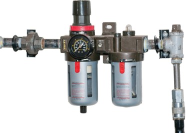
Filter and Regulator
A clean, dry air supply is of prime importance. Moisture in the air lines can damage tools or interfere with their performance. Water in the line tends to dilute and wash away the lubricant and can corrode internal parts. If water gets past the filter, it can enter the regulator mechanism and interfere with its operation. This can lead to erratic air pressure, which affects tool speed and may cause the speed governor (a built-in device that limits RPM) to malfunction. If the governor sticks or fails due to moisture or corrosion, the tool can over-speed, creating a dangerous condition for the operator.
Lubricator
In many tools, the compressed air must contain a lubricant to keep moving parts operating freely. A lubricator, attached between the regulator and the tool, supplies the lubricant in the form of a fine mist. The operator can control the amount of oil misted into the compressed air.
Quick Connectors
Connectors, which are also referred to as quick couplers, make it easier to connect and disconnect supply hoses and tools. The internal end of the connectors is designed to shut off the air flow when the external end is disconnected.
Air Hose
The air hose is made of rubber to make it flexible. The rubber is reinforced with braided thread or wire to make it strong, and coated inside to prevent air from leaking out past the layers. It is available in different lengths and diameters. Hoses can be joined together to reach longer distances. The most common lengths of single hose are 7.5 m and 15 m. The inside diameter must be no smaller than 8 mm. Hoses are available in a variety of pressure ratings and colours.
Air-Impact Wrenches
An air-impact wrench can be used to install or remove fasteners. In addition to rotary motion, there is a hammering effect much like the electric hammer drill to increase torque and make the tool more effective. There is a wide variety of sockets and attachments for this tool. Because impact wrenches are used for both assembly and disassembly, they are reversible.
Pneumatic impact wrenches are made in larger sizes than electrically-operated impact tools and are used more often in heavy-duty applications. Impact wrench sizes are designated by the size of the drive on the nose of the tool. The drive is usually square, with the most common sizes being [latex]\frac{3}{8}[/latex] in., [latex]\frac{1}{2}[/latex] in., [latex]\frac{3}{4}[/latex] in. and 1 in. It is used by inserting it into the drive end of a socket.
Although the sockets used with impact wrenches are similar to the ones that are used with hand tools, they are of a much stronger design in order to absorb the tremendous forces generated.
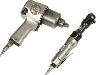
Do not substitute a conventional socket for an impact socket. Conventional sockets can fracture, fly apart, and cause injury.
Air-Operated Grinders
Portable grinders are valuable tools for sharpening other tools, removing burrs, bevelling corners and grinding welding beads. Accessories for brushing, buffing, filing and sanding can be attached to certain models, increasing their versatility.
The grinder spindle speed varies proportionally to grinder size and ranges from 4000 RPM on larger models to over 40 000 RPM on smaller ones. Each grinder has a throttle lever to regulate speed. Certain models have a throttle lever stop-screw that limits throttle depression and may be adjusted to maintain a desired maximum RPM.
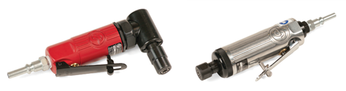
A heavy duty, air-operated grinder, which holds a depressed-centre (cup-shaped) grinder wheel may also be adapted for brushing or sanding. Two hand grips are featured for safe, controlled operation. One handle includes the air trigger or lever. This grinder is available with spindle speeds from 4500 to 7000 RPM.
Air-Operated Drills and Drivers
Pneumatic drills are operated by the force of air moving over the blades of a rotor. This turning force is transmitted to the chuck through a series of gears. The speed of the drill is controlled through its full RPM range by the amount the air-throttle lever or trigger is depressed. Many pneumatic drills are designed with mufflers to reduce the noise caused by the motor.
Chucks for pneumatic drills are made in different sizes corresponding to the drill capacity. Both keyless and key-type chucks are available. Both have three hardened steel jaws that are tightened and released by turning a threaded sleeve.
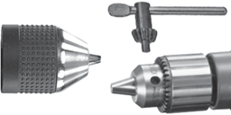
A keyless chuck has a knurled sleeve to permit hand tightening. The key-type chucks are adjusted by inserting a key into a hole on the chuck so that the teeth on the key engage matching teeth on the chuck sleeve.
The portable pneumatic drill is often preferred to an electric drill because it is light and has infinite speed control. In addition, it cannot overheat or be damaged by overloading. Another feature of the pneumatic drill is that it will stop quickly.
Air screwdrivers and nut drivers look very much like air drills. The main difference is in the chuck or bit holder. The tool bit is held in place by a ball-and-spring detent, which facilitates quick changes of bits.
To further enhance the versatility of power screwdrivers, a clutch device or a friction drive can be incorporated, which runs the screw or nut to the required depth or tension.
Air drills can also be operated safely in wet areas, a condition that would make the operation of an electric drill hazardous.
Air Hammers and Chisels
Air hammers are used for riveting, metal cutting and chiselling. They use a reciprocating piston that strikes a tool bit accessory that, in turn, strikes the workpiece.
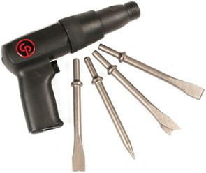
Air hammers and chisels can deliver between 1500 and 4000 blows per minute.
A typical tool bit (chisel) accessory is manufactured from high-quality alloy steel and heat-treated to withstand and deliver repeated blows from the striker piston. Many different bits are available to perform various tasks.
Powder-Actuated Tools
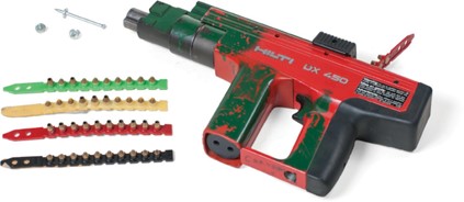
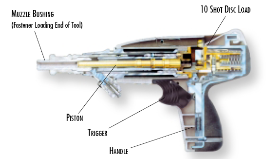
Powder-actuated tools are specially designed tools for driving fastening devices into steel or concrete. They are powered by an explosive powder charge similar to a rifle.
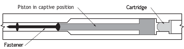
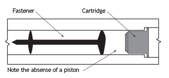
The explosive powder charge creates a rapid expansion of gas that either directly or indirectly, drives the fastener. The indirect system uses a captive piston whose velocity need not be nearly as great as that of a fastener alone to have enough energy to penetrate to the proper depth.
A number of manufacturers have designed different types and models of tools, each tool having specifically designed explosive charges and fasteners. These parts are not interchangeable.
History
Developed in Europe in 1908, the first powder-actuated tool was a high-velocity device that made possible the underwater repair of ships. With welders working inside the ships, divers on the outside used the new tool to nail plates onto the hulls. A captive piston was incorporated into the design to reduce the velocity of the expelled pin.
The tool manufactured by Hilti appeared on the market in 1979. Nearly 10 years later, Hilti introduced an improved design for the captive piston. The result was a safer tool, with the fastening pin travelling at a still lower velocity.
Because of its safety features and efficiency, the low-velocity, powder-actuated tool manufactured by Hilti is the most widely used in the piping industry. Even so, you should know that other tools are available, and that the speed with which they discharge fasteners varies. The speeds below are measured two metres in front of the tool.
To better understand how powder-actuated tools are used in practice, watch the following demonstration from the BCcampus Trades Access Common Core video series, developed by Camosun College: Hilti DX 450 Powder-Actuated Tool (BCcampus Line C Series) [7:09]
This video shows the operation, handling, and typical applications of a powder-actuated fastening tool in construction settings.
As you watch the video, consider:
- What safety precautions are demonstrated?
- What materials is the tool used on?
- Why is training required before using this tool?
Low Velocity
Type: Hilti
This tool operates on the captive piston principle.
Both the fastening pin and the driving piston move at a speed less than 100 m (330 ft) per second.
Medium Velocity
Type: Ramset
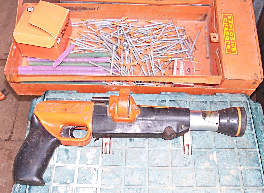
When fired, the fastening pin travels at about 100 to 150 m (330 to 500 ft) per second.
High Velocity
Type: Omark Remington Phillips
These special tools have limited applications. They have no pistons, and the fastening pin is discharged at a velocity above 150 m (500 ft) per second. Speeds of 460 m/sec (1500 ft/sec) are not unusual.
Safety Features
The Hilti powder-actuated tool has a number of built-in safety features:
- A captive piston, already described.
- A built-in device that prevents the tool from firing if it is held at an angle of more than 7° off the work surface. To fire, the tool must be held flat against the work area, at a right angle to the work surface.
- A built-in stop ring or stopping mechanism. Designed to absorb impact, it is the first part of the tool to break down from the force of the impact. When the stop ring becomes deformed, it must be replaced or the tool will not function properly.
Powder Loads and Firing Methods
Low- and high-velocity cartridges are rated according to a colour code; beginning with the weakest rating (grey) through to the strongest rating (purple). Both low- and high-velocity types share the same colour code; the difference is that low-velocity cartridges have a brass case, while the higher- velocity types are encased in nickel.
| Low Velocity (Brass Case) | High Velocity (Nickel Case) |
|---|---|
| Grey (Weakest) | Grey (Weakest) |
| Brown | Brown |
| Green | Green |
| Yellow | Yellow |
| Red | Red |
| Purple (Strongest) | Purple (Strongest) |
Note: When selecting a cartridge, always start with the weakest load for that tool and increase the strength, one step at a time, until the proper fastening is obtained. Re-driving a fastener is not recommended, as it can damage the tool and weaken the grip of the fastener.
Cartridges
There are two designs used for cartridges: crimped and wadded. Both provide the same power. Hilti uses the crimped design and paints the cartridge tip to identify the strength of the powder load (grey to purple). The paint also acts as a waterproof barrier to keep the cartridge dry.
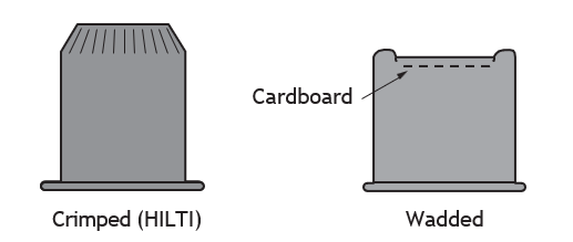
Wadded cartridges are not used by low-velocity or captive piston tools because the wads could plug the vent ports needed with the captive piston system.
Firing Methods
The cartridges for powder-actuated loads are either:
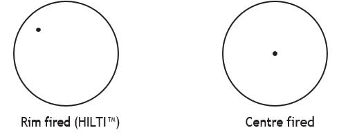
- Rim fired (the Hilti method) or
- Centre fired
Types of Fasteners
Fastening pins are made of specially hardened steel. For fastening into concrete, the shank (the end of the fastener being driven into the concrete) is smooth. For fastening into steel, the shank is knurled, meaning that the tip has a series of small ridges to aid fastening.
Each tool model will accept only the type of fastener specially designed for it. Therefore, it is very important that the right fastener is selected for the tool.
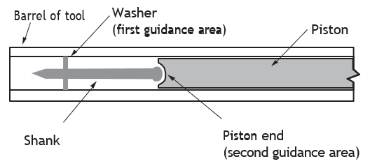
In designing fasteners for its tool models, Hilti has incorporated a double guidance system.
Interpretation of Fastener Codes
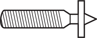
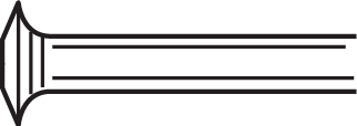
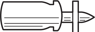
The follow table describes the fastener by its corresponding code.
|
Code |
Meaning |
Illustration |
|---|---|---|
|
DN |
Dome head nail (small) |
|
|
W |
Threaded |
|
|
NK |
Round head nail |
|
|
DS |
Dome head nail (large) |
|
|
TB |
Eyelet fastener |
|
|
E |
E in front of any code indicates that the fastener has a knurled shank and is used for steel only. |
|



Example 1:
Code W6-20
W – designates threaded
6 – designates a thread diameter of 6 mm ([latex]\frac{1}{4}[/latex] in.)
20 – designates a thread length of 20 mm
Note: The piston must be changed for each threaded fastener so that the bore in the piston matches the fasteners. Thus, codes W6-11, W6-20, and W6-30 call for pistons with different bores, because each threaded fastener has a different length.
Example 2:
Code W6-20-22-S-12
W – a threaded fastener
6 – thread diameter – 6 mm
20 – thread length – 20 mm
22 – shank length – 22 mm
S – steel washer
12 – washer diameter – 12 mm
Note: Three types of material are used for washers.
S – steel
P – plastic
D – dual (a combination of plastic and steel)
 Self-Test B-2.1: Describe Portable Power Tools Used in the Pipe Trades
Complete Self-Test 2.1 and check your answers.
If you are using a printed copy, please find Self-Test A-2.1 and Answer Key in the Appendix at the end. If you prefer, you can scan the QR code with your digital device to go directly to the interactive Self-Test.

References
BC Industry Training Authority. (2019). Piping trades apprenticeship program: Use Tools and Equipment—Level 1 harmonized [Binder]. Crown Publications, Queen’s Printer for British Columbia. https://www.crownpub.bc.ca/Product/Details/7960000261_S
Camosun College. (2015). Trades Access Common Core Competency C-2: Describe Common Power Tools and Their Uses. Victoria, B.C.: Crown Publications. Download for free from the B.C. Open Textbook Collection (https://open.bccampus.ca/browse-ourcollection/find-open-textbooks/).
Camosun College. (2019). Line C: Tools and Equipment—Competency C-2: Describe Common Power Tools and Their Uses (Rev. ed.) [Learning guide]. BCcampus. https://collection.bccampus.ca/textbook/zAYtfTec/
Camosun College. (2022). Hilti DX 450 [Video]. BCcampus. https://media.bccampus.ca/media/Hilti%20DX%20450/0_qkdz82jw
Media Attributions
All figures are sourced from Industry Training Authority (2019) and/or Camosun College (2019) and are used under the Creative Commons Attribution 4.0 (CC BY 4.0) licence unless otherwise noted. Images copyrighted by the BC Industry Training Authority are licensed under a Creative Commons Attribution-NonCommercial-ShareAlike 4.0 (CC BY-NC-SA 4.0) licence.
RIDGID tool images are used with permission from Emerson Professional Tools. Some of these images may have been carried forward from SkilledTradesBC learning resources; however, permission has been obtained directly from Emerson Professional Tools for their use here.
- Figure 49 Handheld drain auger is by Pgdp123 on Wikimedia Commons and is used under a CC BY 3.0 license.
- Figure 58 Sectional drain machine is from RIDGID TOOLS/Emerson Professional Tools, and is used with permission.
- Figure 60 Water jetter is from RIDGID TOOLS/Emerson Professional Tools, and is used with permission.
- Figure 64 Portable yellow air compressor [AI-generated], is by Muhammad Abdullah on Freepik, and is used under the Freepik Terms of Use.
- Figure 66 Powder-Actuated tool diagram is by Dustinmck on Wikimedia Commons, and is used under a CC BY-SA 4.0 license.
- Figure 68 Ramset gun by Bill Bradley [billbeee] on Wikimedia Commons is used under a CC BY-SA 3.0 license.
A tool or piece of equipment that is easy to carry and move from one place to another so it can be used in different locations. Portable tools are often cordless and may use a rechargeable battery. (Section B-2.1)
When two lines or surfaces meet at a right angle (90°). One line goes straight up or across from the other. (Section B-2.1)
When two lines or surfaces run in the same direction and stay the same distance apart, so they never meet or cross. (Section B-2.1)
The distance between the teeth on a saw blade. It helps determine how fast and how smoothly the saw cuts. (Section B-2.1)
The back edge of a saw tooth that slopes downward after the cutting tip. (Section B-2.1)
The forward-leaning edge of a saw tooth that helps pull the blade into the material during cutting. (Section B-2.1)
The curved space between two saw teeth that collects and clears chips or sawdust while cutting. (Section B-2.1)
A saw blade designed to cut wood along the grain. The teeth are shaped to remove wood quickly and make long, straight cuts. (Section B-2.1)
A saw blade designed to cut wood across the grain. The teeth are shaped to make smoother, cleaner cuts. (Section B-2.1)
A saw blade that can be used for both ripping and crosscutting. It is made to handle general cutting jobs. (Section B-2.1)
A combination saw blade with chisel-shaped teeth that cut wood cleanly and efficiently when ripping or crosscutting. (Section B-2.1)
A circular saw blade designed to cut metal. It is made from strong materials and has specially shaped teeth that allow it to cut through metal safely and efficiently. (Section B-2.1)
A circular cutting disk made from abrasive material that grinds through metal or other hard materials instead of cutting with teeth. It is commonly used on chop saws or grinders to cut metal. (Section B-2.1)
A circular saw blade designed to cut hard building materials such as brick, concrete, and stone. It is made with very hard materials so it can grind through masonry. (Section B-2.1)
A saw blade with small tips made of carbide, a very hard metal, attached to each tooth. The carbide tips help the blade stay sharp longer and cut hard materials more easily. (Section B-2.1)
(Also known simply as a recip saw or Sawzall); a power saw with a blade that moves back and forth quickly to cut through wood, metal, or plastic. (Section B-2.1)
A power tool that uses a rotating abrasive wheel or blade to cut metal, pipe, or other materials. (Section B-2.1)
A circular cutting wheel made of abrasive material that grinds through metal or other hard materials instead of cutting with teeth. It is commonly used on power saws or grinders to cut metal. (Section B-2.1)
A handheld power saw that uses a continuous loop blade to cut metal, pipe, or other materials. (Section B-2.1)
A circular saw blade designed to cut metal using strong materials and specially shaped teeth. (Section B-2.1)
A saw blade made from carbon steel that is strong and flexible, often used for cutting wood or soft metals. (Section B-2.1)
A saw blade made from steel that is harder than carbon steel and can handle faster cutting speeds. (Section B-2.1)
A saw blade made from a special steel that stays strong and sharp even at high cutting speeds and temperatures. (Section B-2.1)
A band-saw tooth pattern with evenly spaced teeth designed for smooth cutting. (Section B-2.1)
A band saw blade with teeth that lean forward to cut quickly and remove material efficiently. (Section B-2.1)
A band-saw blade with widely spaced teeth that helps clear sawdust and is useful for cutting softer materials. (Section B-2.1)
A pattern of band-saw teeth where one tooth bends left, the next bends right, and the next stays straight to help clear chips while cutting. (Section B-2.1)
A band-saw tooth pattern where small groups of teeth are bent slightly in alternating directions to make smooth cuts in thin materials. (Section B-2.1)
A clamping device on a drill that uses three jaws to hold a drill bit or other tool securely in place while it spins. The jaws tighten or loosen together to keep the bit centered. (Section B-2.1)
A feature on a power tool that allows the operator to control how fast the tool runs. The speed can be increased or decreased depending on the task being performed. (Section B-2.1)
Common drill bits with spiral grooves that remove material as the bit drills into wood, metal, or plastic. (Section B-2.1)
A drill bit designed for wood that pulls itself into the material and cuts quickly with several sharp cutting edges. (Section B-2.1)
A drill bit with a spiral shape and a pointed tip used for drilling deep, clean holes in wood. (Section B-2.1)
A drill bit used to widen the top of a hole so the head of a screw can sit flush with or below the surface of the material. (Section B-2.1)
Drill bits with tips made of carbide, a very hard material that helps the bit stay sharp and drill through tough materials like masonry or hardened metal. (Section B-2.1)
A circular cutting tool with teeth on the edge used with a drill to cut large round holes in materials such as wood, plastic, or metal. The center drill bit helps guide the saw while cutting. (Section B-2.1)
A power drill that combines rotating motion with a hammering action to drill into hard materials like concrete or masonry. (Section B-2.1)
A heavy-duty power tool used to break, chip, or remove concrete, masonry, or other hard materials. (Section B-2.1)
A power drill designed with the chuck set at a right angle to the motor so holes can be drilled in tight or hard-to-reach spaces; known by names like Hole-Hawg. (Section B-2.1)
A mechanical fitting that attaches to a pipe to create a branch outlet connection. (Section B-2.1)
A method used to cut into a pipe while it is still in service and under pressure, allowing a new connection to be added without shutting off the flow inside the pipe. (Section B-2.1)
A special drill used to cut an opening in a pipe so a branch connection can be added without removing the pipe. (Section B-2.1)
Power tools used to cut large, round holes in materials such as concrete, brick, or stone using a hollow drill bit. (Section B-2.1)
A portable power tool that uses a rotating grinding wheel or disk to grind, cut, smooth, or polish metal and other materials. (Section B-2.1)
A handheld power tool that uses a rotating grinding wheel or disk mounted on the side of the motor to grind, cut, or smooth metal and other materials. It is commonly used for metal work and pipe preparation. (Section B-2.1)
A round wheel made of abrasive material used to grind, shape, smooth, or sharpen metal and other materials. (Section B-2.1)
The measure of how strongly the abrasive grains are held together in a grinding wheel. (Section B-2.1)
The amount of abrasive grains packed into a grinding wheel. A wheel with high grain density has more grains close together, while a wheel with low grain density has fewer grains with more space between them. (Section B-2.1)
A grinding wheel with large abrasive grains spaced farther apart to remove material quickly. (Section B-2.1)
A grinding wheel made with small abrasive grains packed closely together to produce smoother and more precise grinding. (Section B-2.1)
A powered tool used to turn pipe-threading heads and cut threads on pipe quickly. (Section B-2.1)
A pipe-threading tool with a head that can open or “drop” to quickly release the pipe after threads have been cut. (Section B-2.1)
A method used to join thermoplastic pipes by heating the pipe ends until they soften and pressing them together to form a strong joint. (Section B-2.1)
A type of plastic pipe that softens when heated and hardens again when cooled. (Section B-2.1)
A group of plastics made from simple chemical compounds called olefins. Common examples include polypropylene (PP) and polyethylene (PE). These plastics are lightweight, strong, and resistant to chemicals, so they are often used to make pipes, fittings, and other plumbing materials. (Section B-2.1)
A flexible tool used to clear blockages in pipes and drains. It is pushed into the pipe and rotated to break up or pull out the material causing the clog. (Section B-2.1)
A portable drain-cleaning machine used to remove clogs in sinks, floor drains, and small pipes. It rotates a flexible cable (snake) inside the pipe to break up or pull out blockages. (Section B-2.1)
A drain-cleaning machine that stores a long flexible cable inside a rotating drum. The cable is fed into a pipe to break up or remove blockages in drains and sewer lines. (Section B-2.1)
A drain-cleaning machine that uses several short sections of cable connected together to clear blockages in pipes. Each section is added as needed, allowing the cable to reach farther into the drain. (Section B-2.1)
A drain-cleaning machine that uses a high-pressure stream of water to break up and wash away grease, debris, and other blockages inside pipes. (Section B-2.1)
A tool used to temporarily freeze the water inside a pipe so repairs can be made without shutting off the entire water system. The frozen water forms a plug that stops the flow while work is done. (Section B-2.1)
A temporary blockage of ice formed inside a pipe when the water in the pipe is frozen. The ice stops the flow of water so repairs or changes can be made without shutting off the entire system. (Section B-2.1)
A device that controls the maximum speed of a machine or motor to keep it running at a safe and steady rate. (Section B-2.1)
(quick couplers); Devices or fittings used to join two pieces of equipment, pipe, hose, or electrical components so they can work together properly. (Section B-2.1)
A power tool that uses compressed air to quickly tighten or loosen nuts and bolts by delivering strong turning force in short bursts. (Section B-2.1)
(Often called a Hilti gun or Ramset gun after their manufacturing companies); A power tool (like a nail gun) that uses a small explosive charge (similar to a firearm cartridge) to drive fasteners such as nails or pins into hard materials like concrete or steel; process is known as direct fastening or explosive fastening. (Section B-2.1)