B-1.3 Use Levelling Equipment
Levels Used to Establish Elevations
Levels are instruments used to project a level line 360° around their axis in order to transfer, measure or set elevations. There are two broad categories of levels: optical and electronic. Optical levels, also known as builder’s levels, generally need two people to operate them. One person looks through a telescope and interprets the reading of a sighting from a levelling rod, which is held by the other person. Electronic levels rotate a light beam and only require one operator, who uses the rod along with a sensor that picks up the light beam.
Optical Level Electronic Level With a Sensor
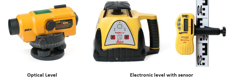
Types of Builder’s (optical) levels
Optical levels are high-powered telescopes equipped with crosshairs and centrally mounted on a bearing so that they can rotate only horizontally. They are different from transits or theodolite levels. Transits and theodolites (Figure 2) can measure horizontal and vertical angles and are used as surveying tools.
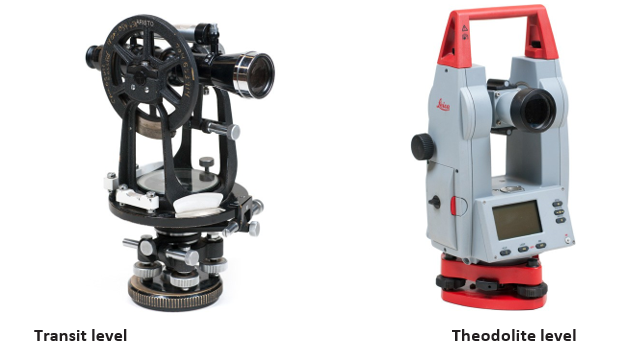
Builder’s levels are designed for horizontal rotation only and therefore are only used for horizontal leveling. This learning resource will not cover transits or theodolites.
An optical level can be used to perform the following tasks:
- Find the elevation of selected locations. Given a benchmark location and elevation, you can find the elevations of a series of other given locations.
- Establish the elevation of an object. Blueprints provide the information needed to do the following:
-
- Set the elevation of a slab
- Set the height of a wall
- Set the invert (lowest inside point of a pipe’s inner surface) elevation and slope of a pipe
Optical levels can be categorized as manual or automatic, according to the way they are set up. There are two types of manual levels: “dumpy” and tilting.
“Dumpy” Levels (also known as 4-pin levels)
Although no one seems to know for certain where the term dumpy came from, it’s widely accepted as the most rudimentary of all the builder’s levels. It consists of a short telescope mounted to a table that is adjustable using thumbscrews or “pins.” A spirit vial mounted below the telescope contains an air bubble in a small amount of alcohol, which is used instead of water so that freezing isn’t a problem. The vial is similar to those found in carpenter’s or “torpedo” levels. Dumpy levels are the least expensive and least sensitive of all the builder’s levels and are generally known as being the hardest to correctly set up. They traditionally have four pins, while the others typically have only three.
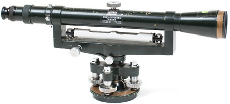
Tilting Levels
A tilting level (also known as split-bubble or engineer’s levels) is so named because the horizontal plane of the telescope can be raised or lowered very slightly through a limited arc without impairing the accuracy of the reading. This is done to ensure that the reading taken is precisely level.
A fish-eye bubble provides for general levelling, and a bubble tube is usually mounted alongside the telescope and is viewed through a separate eyepiece for fine-tuning. For example, an optical sighting arrangement that brings opposite halves of a bubble image (split bubble) into alignment. Illustrated later in this section.
Tilting levels are generally more compact, more sensitive and more expensive than dumpy levels. They usually have only three pins for levelling the table, which makes them easier to set up than the dumpy, although some are made in a 4-pin configuration.
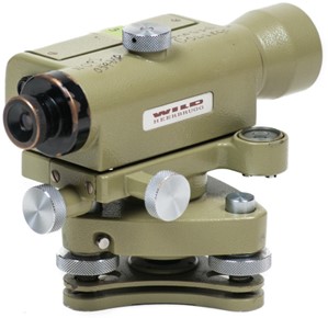
Automatic Levels
Automatic levels (also known as self-levelling levels) have only a fish-eye bubble that needs manual centring. Inside the instrument is a prism, also known as a compensator, suspended by very fine wires. An automatic level, if shaken lightly, will make a slight “jangling” sound from within, evidence of the prism and wires. The prism fine-tunes the levelling, which makes setting up the automatic level very quick and easy. Once the fish-eye bubble is centred, the telescope can be rotated through 360˚ without the need for any further adjustment.
Optical instruments share a number of features:
- crosshairs and stadia lines inside the viewfinder
- an eyepiece focus (for the crosshairs)
- field-of-view focus (for the levelling rod)
- a [latex]\frac{5}{8} \text{"}[/latex] female thread connection on the footplate (for attachment to the tripod)
- an azimuth adjustment (for precise sideways movement)
Some varieties may or may not have an azimuth clamp and screw for moving the telescope sideways.
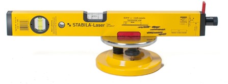
Types of Electronic Laser Levels
The use of laser and electronic levels has now become very commonplace on the job site. They are easy to use and have a distinct advantage over optical levels because they require only one operator. One worker using a laser or electronic level can perform the same job as two workers using an optical level. Electronic levels also allow many workers on large jobs to use the same instrument setup at one time with different receivers. They are ideal for setting suspended ceilings, levelling concrete floors, setting drainpipes, grading roads and building lots, and performing other tasks that are usually done with a standard optical level. It is important to read the manufacturer’s instructions before using these levels. Do not exceed the maximum range of the instrument and complete an accuracy check on a regular basis.
Laser levels
The word laser is an acronym for “Light Amplification by Stimulated Emission of Radiation.” A mixture of helium and neon gases is used to emit a very narrow beam of light that does not grow larger as it moves away from the source, which in this case is the laser level (Figure 6). In low light conditions the laser beam can be seen as bright red. Some manufacturers use a green laser beam, which is easier to see in daylight conditions. In bright sunlight, a sensor or detector is required in order to read the beam.

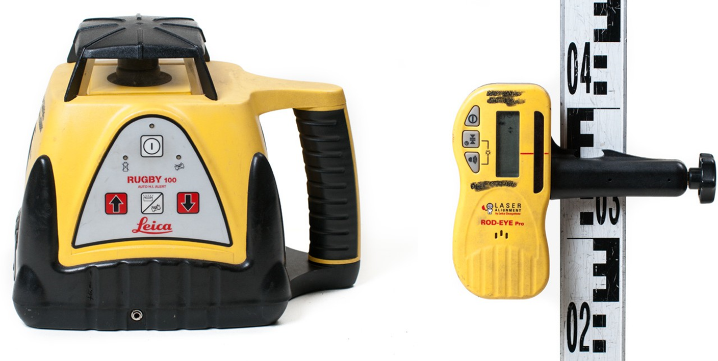
Electronic Laser Levels
With electronic levels (Figure 7) the beam can be directed to any point, or it can be rotated continuously at various speeds and controlled remotely. A beam detector or sensor must be used to locate this infrared laser beam.
Using Electronic Laser Levels
Electronic laser levels depend on an electrical power source such as batteries, a 12-volt source from a truck or car, or a 110 VAC adapter. Set-up is very easy. A bubble level or fish-eye is used to rough- level the instrument. When the bubble is in the ring, the instrument levels itself with its motor- driven levelling system. If, during operation, the instrument is knocked and moved beyond the limits of self-levelling, the beam shuts off.
The instruments can be supported in several ways. The most usual supports are tripods of various heights. They can also be clamped to columns, or have small feet attached so that they can be set into or on drainage pipes. Suspension frames are available to hold the instruments and aim them into pipes.
Sensors or Detectors
Electronic laser levelling instruments can be operated by a single person. When the instrument is set up and running, a level reference plane is created that can be seen by eye or detected with the sensor or detector (Figure 8).
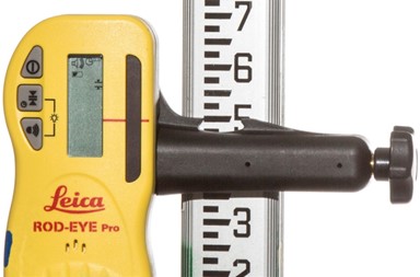
The sensors or detectors operate on batteries and have a narrow window through which the beam can be detected. When the beam is sensed, the detector shows a small, colored light or emits a sound. Sensors or detectors can be attached to the levelling rod or can be used by themselves to locate instrument height on walls or forms.
Targets
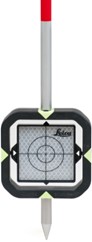
Targets (Figure 9) are made of clear plastic with a cross marked on them. They are used to set levels with a laser level for items such as ceiling T-bars, concrete screeds or drainage pipes, using a direct or rotating beam. The object (with target attached) is lowered, raised or moved sideways until the beam is located at the target cross.
Checking Laser Level Accuracy
Many laser levels are designed to allow the operator to calibrate the unit. The manufacturer’s instructions will include the method. Often it is as simple as setting up 50 meters from a wall, marking the location, and then rotating the instrument 360° and marking again. If the two marks are not within tolerance of each other, then turn the instrument on by pushing two buttons at once and adjust the beam up or down by pushing buttons. Then rotate the instrument 90° and make a third mark. Rotate the instrument another 180° and make a fourth mark. The instrument is turned on by pushing another combination of buttons, and then the beam is adjusted. In this way, both the X and Y axes are recalibrated.
Pipe Laser Levels
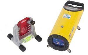
Pipe laser levels (Figure 10) are specially designed for installing pipes requiring a constant grade and for setting grades for areas requiring drainage. When laying pipe, the laser is set up at the end of the pipe (either inside or on top) and set to the desired slope of the pipe. The target is located at the end of the pipe and the pipe is moved until the target is centered to the beam. Pipe laying can continue until a change of direction is required or the maximum range of the beam has been reached.
Five-Way Laser Levels
A five-way laser level is used mainly for laying out 90° corners, for levelling and for plumbing up or down. It can also be used as an electronic chalk line. There are five laser beams (Figure 11); one shoots down, one shoots up, one shoots straight forward. The last two are at 90° on both sides to the forward beam.
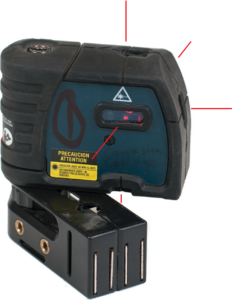
The unit self-levels, and the beams are bright enough that a sensor is not required. Most five-way levels are accurate only up to between 10 and 30 meters, as the laser beam becomes too wide past that point.
Five-way laser levels can be set on the floor, mounted on a tripod or clamped to an object. Follow the manufacturer’s instructions; be careful not to exceed the rated distance. As the laser beams are quite bright, extra care should be taken not look into the beams.
Parts of a Tilting Level
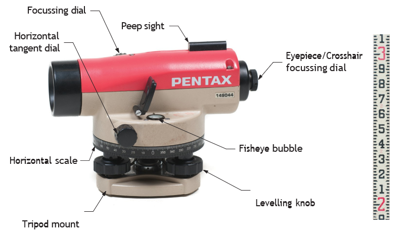
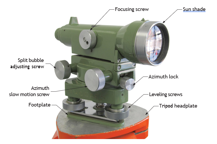
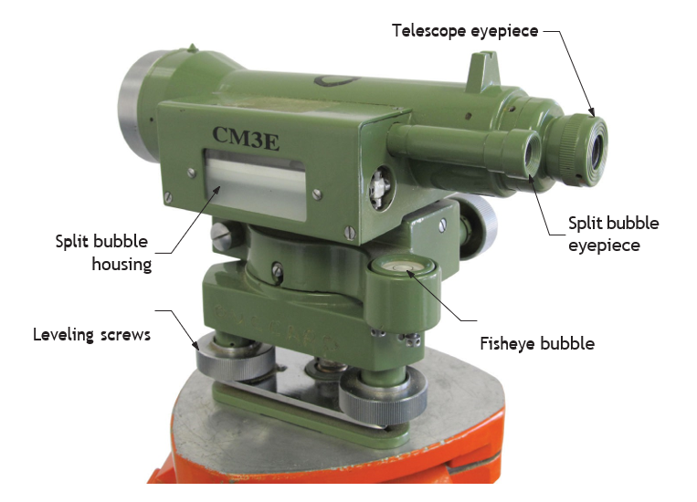
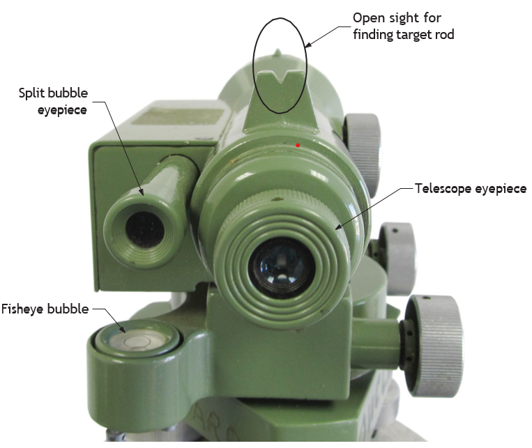
Figures 12 to 15 identify the major working parts of a tilting level. Note that a tilting level has some parts that are not found on either a “dumpy” or an automatic level. The functions of these parts and some others are described on the following pages.
Telescope Eyepiece
The eye is positioned at the telescopic eyepiece when a reading is being taken. The eyepiece has a knurled adjustment ring for focusing the crosshairs.
Crosshairs/Stadia Hairs
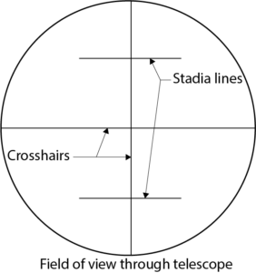
The crosshairs are lines that are etched on a piece of glass, sometimes called the fixed reticle. The crosshairs are a pair of vertical and horizontal lines (Figure 16). Readings are taken at the horizontal crosshair. The rod can be lined up plumb in one direction using the vertical hair. The vertical hair is further divided by lines above and below the horizontal crosshair, called stadia lines, which are used to measure distance.
Telescopic Barrel
The telescopic barrel contains the lenses and focusing ratchet mechanism. The lens at the front, or the end opposite the eyepiece, is called the objective lens.
Focusing Screw
The focusing screw brings the object seen through the eyepiece into sharp focus by moving the lenses inside the barrel.
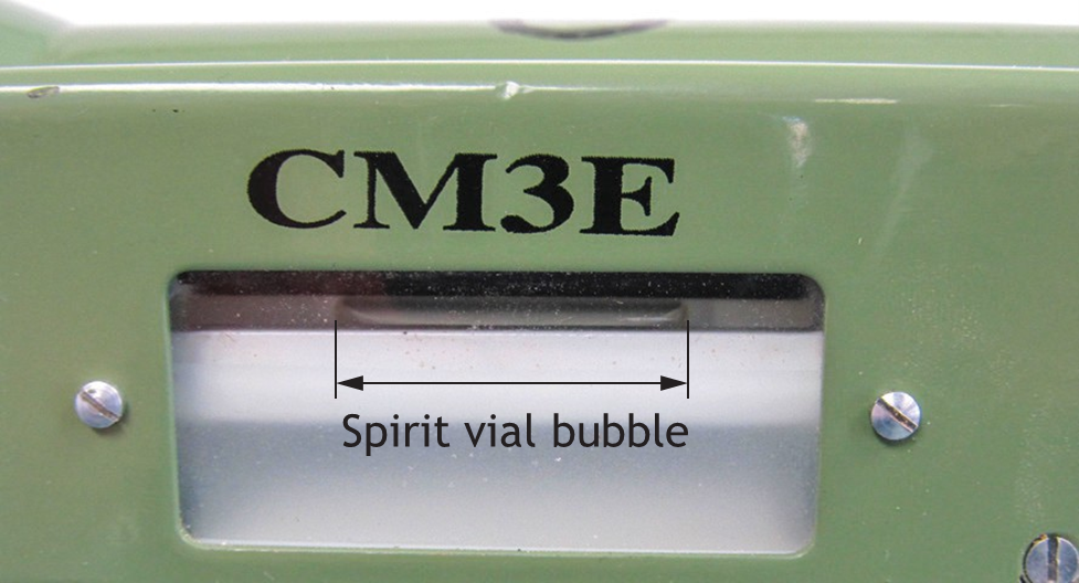
Levelling Split Bubble
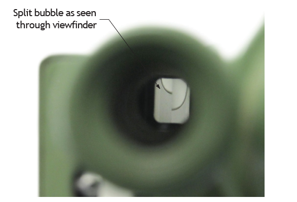
The levelling split bubble (Figure 17) can be located above or below the barrel, as on a dumpy level, or alongside it, as on a tilting level. The length of the bubble expands and contracts with changes in temperature.
Fish-Eye Bubble
The fish-eye bubble is used to roughly set to level the line of sight of a tilting level, or to accurately set up an automatic level. It is attached to the levelling head.
Horizontal Tangent Screw
This screw is also referred to as the slow motion or azimuth screw. It is used to slowly rotate and accurately aim the telescope horizontally. Usually it is located just below the objective lens. It will only operate if the horizontal (azimuth) clamp is tightened.
Horizontal Tangent Screw Clamp (Azimuth Lock)
This clamp can be loosened to allow the barrel of the instrument to be freely swung horizontally, and to roughly aim the instrument. Once the instrument is roughly aimed, the clamp is then tightened, and the fine horizontal sighting is done with the slow-motion screw.
Levelling Screw / Tilting Screw
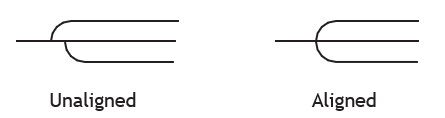
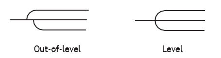
The levelling screw is used to bring the instrument perfectly horizontal, parallel to the line of sight. It is usually located just below the eyepiece and is activated by turning in direction to center the bubble in the level vial. Sometimes it is aided by a coincidence optical mechanism, known as a split bubble. You must line up both halves of the bubble in the mirror to level the instrument (Figure 18).
The sunshade is a short tube attached to the objective lens end of the barrel to eliminate sun glare.
Tripod
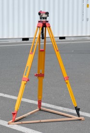
The footplate of a builder’s level is fastened to the headplate of a three-legged stand known as a tripod by a [latex]\frac{5}{8} \text{"}[/latex] NC bolt fixed to the underside of the tripod’s headplate. The tripod has three extendable legs with feet that are pointed and have a horizontal peg that allows for them to be firmly pressed by foot into soft ground (Figure 19).

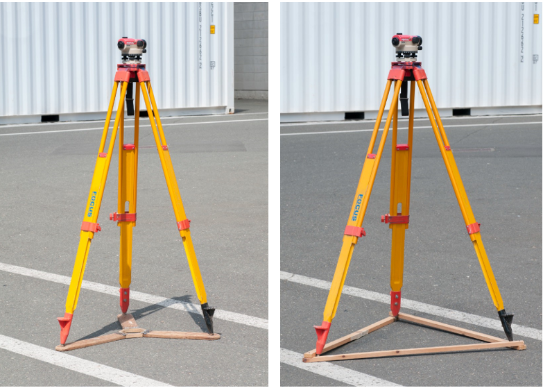
There are also rubber tips and suction cups available for use on smooth floors. The top pivot pin of each leg can be tightened or loosened to create more or less resistance to opening or closing the legs. When used on fairly rough terrain, a light closing force would be adequate, whereas on smooth, slippery surfaces a more positive force would be advantageous in order to keep the tripod legs from splaying outward. If the tripod does not have rubber feet or suction cups, a triangle of 1×4 wood can be used, with the tripod feet pushed into the corners (Figure 20). It is of utmost importance to not move the tripod at all once it is set in position; to do so would necessitate a re- setting of the level.
Levelling Rods
Levelling or target rods (Figure 21) also known as Philadelphia rods, are used to take readings on sights. They can be either hinged or telescopic and can be made of wood, fibreglass or aluminum alloy. The units of measure (scales) can be metric or imperial.
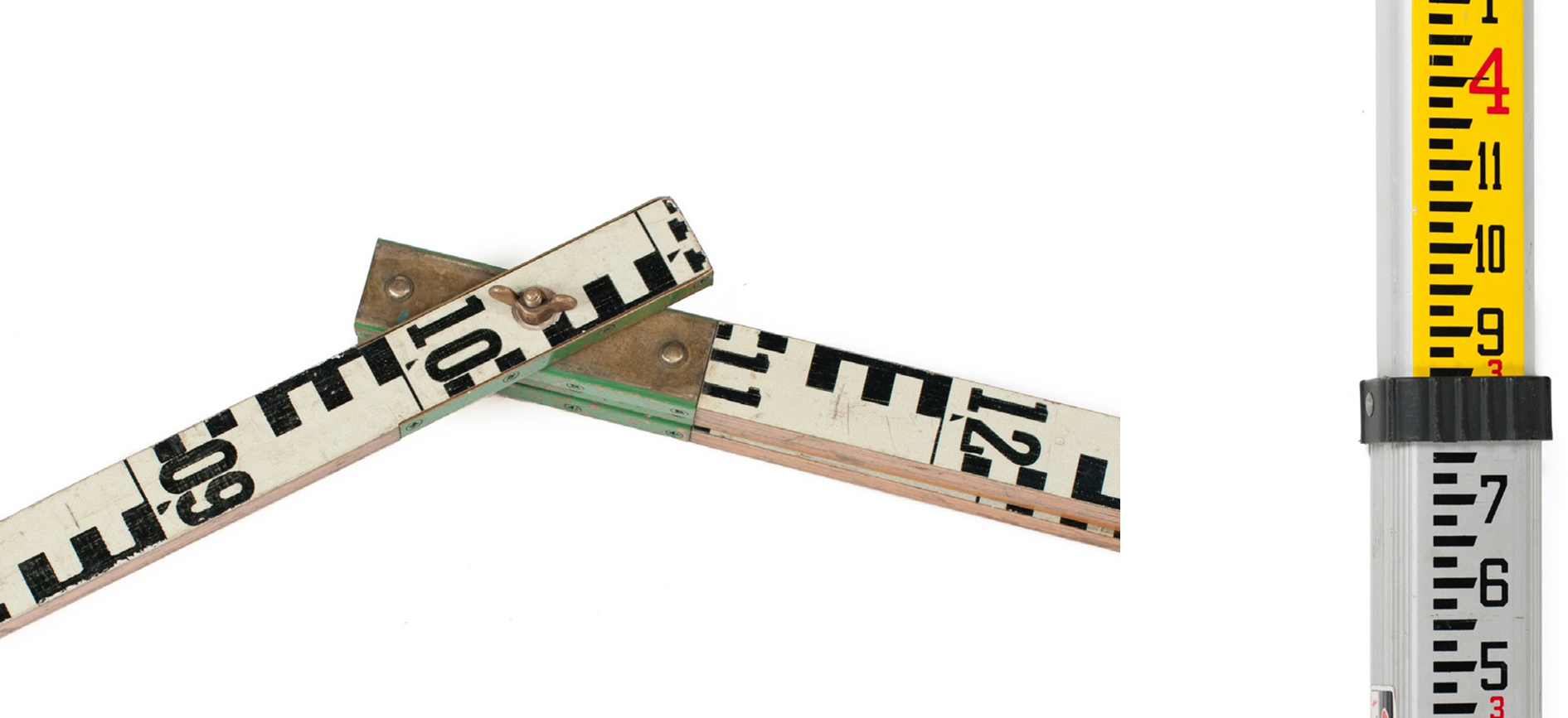

There are several methods of displaying the scales. The type suited to construction could be the segmented type with a Scotchlite face as they are easily collapsed for use in confined spaces, and a light source can be shone on the scales for easy reading in poor light conditions.
Metric Rods
Scales in the metric system are generally shown in 10-mm (1-cm) divisions (Figure 22). It has been the practice when using metric rods to visually break down the 10-mm divisions. With a bit of practice one should have no difficulty in making rough estimates to the closest millimeter (±1 mm), which is considered an acceptable tolerance. For more accurate readings, a target that has the 1-cm scale divided up into millimeters can be fitted on the rod, or a portion of a metric tape measure can be held with the rod.
Imperial Rods
The imperial system of measurement, which uses inches and feet, is used on both the architect’s rod and the engineer’s rod The architect’s rod is broken into feet, inches and fractions of an inch, whereas the engineer’s rod is divided into feet and hundredths of a foot. You can quickly tell if it is an architect’s or engineer’s rod by looking for the 11-inch marking. The engineer’s rod does not show the 11-inch mark, while the architectural rod does.
Architect’s rod readings (Figure 23) are divided into [latex]\frac{1}{8} \text{"}[/latex] increments, which are generally considered to be the accepted tolerance for field readings. The marks with the point at the end are at the 0″ mark and the [latex]\frac{1}{2} \text{"}[/latex] mark.
Engineer’s rod readings (Figure 23) are divided into 0.01′ ([latex]\frac{1}{100} \text{'}[/latex]) increments. The marks with the point at the end are at the 0.1′ ([latex]\frac{1}{10} \text{'}[/latex] or [latex]\frac{10}{100} \text{'}[/latex]) mark and the 0.05′ ([latex]\frac{5}{100} \text{'}[/latex]) mark.
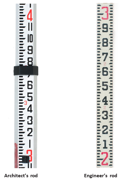
Care should be taken when reading the engineer’s rod: a reading of 0.6′ would be 7.2″ or 7 3/16″ , not 6″!
Note – When geodetic (accurate measurements of the earth) elevations are needed, either the metric or engineer’s scales is used.
Stadia Lines
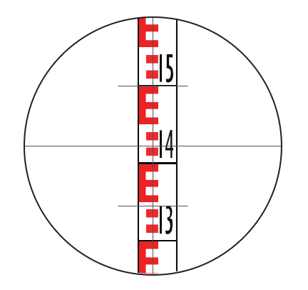
Stadia lines (or hairs) (Figure 24) are used to find the distance from the instrument to the rod.
The accuracy of the stadia line distance is totally dependent upon how accurate the rod readings are. For example, if the stadia line reading was accurate to 1 millimeter, then the resulting distance would be accurate to ±100 mm. The stadia line ratio is 1:100, no matter what the rod units are.
To find the distance:
- Take the readings of the top stadia line and of the bottom stadia line.
- Subtract the smaller from the larger.
- Multiply the answer by 100.
The result is the distance from the instrument to the rod. See examples 1 and 2 below. The concept will work with an architect’s, engineer’s or metric rod.
Example 1
Top stadia line reading = 1.500 m
Bottom stadia line reading = 1.345 m
Difference between readings = 0.155 m
Distance to the rod = 0.155 × 100 = 15.5 m
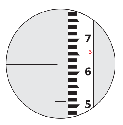
Example 2
Top stadia line reading = 3.74′
Bottom stadia line reading = 3.51′
Difference between readings = 0.23′
Distance to the rod = 0.23′ × 100 = 23′
Using the Level Rod
To ensure that accurate information is obtained, the level rod must be held plumb whenever a reading is taken. The instrument operator can see through the telescope whether the rod is being held plumb in one direction only. To obtain plumb in the other direction, the instrument operator must give a signal to the rod person to slowly move the rod through a small arc forward and backward, so that the lowest reading can be taken if the rod is being held erect, or the lowest reading if the rod is inverted. The illustration in Figure 103 should help in understanding this.
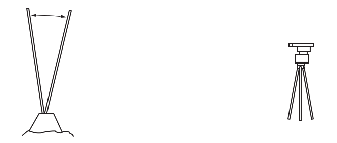
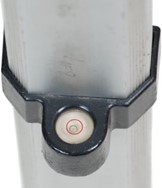
The device shown in Figure 28 contains a fish-eye bubble and can be used by the rod person to plumb the rod.
A pointed target (like a sharp pencil) is moved up and down on the rod by the rod person as directed by the instrument-person. The rod reading is taken by the rod person and relayed to the instrument person.
Hand Signals
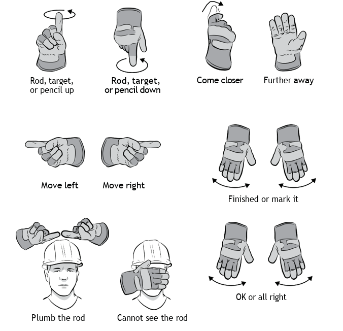
Hand signals should be used for communication between the instrument person and rod person. These are necessary so that the work can be done efficiently, without yelling or shouting to each other. Sometimes the distance between the instrument person and the rod person is too great or it is too noisy for verbal communication.
Figure 29 shows the hand signals that should be used.
Set-up and Care of Optical Levels
Tripod Set-Up
If possible, set up midway between the backsight and foresight locations.
Using the leg thumbscrews or cam locks, extend the legs enough so that, when set up, the instrument will be at a comfortable height for readings. A good suggestion is to have all three legs closed and in contact with the ground, and the tripod top plate at chin level. This will put the mounted instrument at a comfortable height. Snug their locking screws up, but do not over tighten the screws. Grasp two of the legs and plant the third out in front of you into the ground. Spread the tripod legs about 900 mm (3 ft.) apart, draw the two legs back and set the feet firmly into the ground (farther apart if windy).
If the ground is sloping, put two legs on the downhill side and the other one uphill. Use a triangular wooden frame if setting up on a floor with a smooth surface such as concrete, where the feet of the tripod cannot dig in. Once the feet are set, adjust the leg lengths so that the top plate of the tripod is level by eye.
Make sure the tripod is secure against any movement by grasping the head and gently trying to move it in a horizontal circle. If there is any movement, then something is loose and all connections should be tightened up before proceeding to mount the instrument. If possible, try to stand between two of the legs when sighting, rather than straddling one of the legs and bumping the instrument. Attach the instrument to the tripod. Tighten the locking screw firmly, but do not over tighten.
Levelling the Instrument
Levelling instruments are used to set, transfer and measure elevations. Levelling the instrument so that the line of sight is in a level position is the most important procedure to obtain accurate levelling work. There are different methods for instruments with four or three levelling screws, and for the quick-set type of instrument. Each will be described separately.
If the instrument goes out of level for any reason, it must be readjusted to a level position before continuing to take readings.
Levelling Instruments with Four Levelling Screws (Pins)
Most instruments with four levelling pins use a tubular level vial. A tubular level vial is a curved glass tube filled with alcohol that has a bubble of air trapped inside. The amount of curve in the vial is very slight, sometimes not even able to be seen by eye. The air bubble will move to the highest point of the curve; if the vial is tipped either left or right, the air bubble will move toward the higher end.
To level the instrument, follow these steps:
- Make sure all the levelling screws are loose and equally set for height.
- Position the telescope barrel over a diagonal pair of levelling screws and take up any slack on these screws so the instrument will not wobble horizontally.
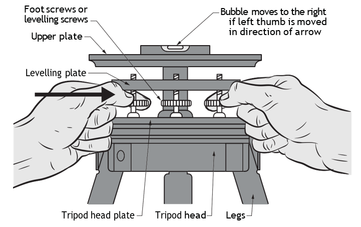
- Turn the levelling screws in opposite directions, using the direction of the left thumb to guide the level bubble roughly to centre. This is referred to as the “rule of the left thumb,” which states that the level bubble will always travel in the same direction as that of the left thumb (Figure 30).
- Rotate the telescope 90˚ so it is directly over the other two pins, and repeat the process in step 3.
Continue to repeat steps 3 and 4 until the bubble does not move when the telescope is slowly rotated 360 degrees.
Levelling Instruments with Three Levelling Screws (pins)
Instruments with three pins are quite different from those with four pins. The pins on a three-pin instrument always hold the instrument from rocking, so they do not need to be tightened up to take out any slack.
Instruments with three pins usually have two levelling devices: a rough levelling device, which is usually a fish-eye bubble, and a fine levelling device, which could be either a split-bubble or an automatically-adjusting hanging prism.
The foot screws on three-pin levels do not snug up, but it is possible to turn them all the way to the end of their travel, and this will give you the feeling that they are not able to turn any more. To allow full movement of the foot screws, position each of the foot screws halfway in its travel prior to attempting to level the instrument. There is often a mark used to indicate halfway.
Adjusting a Fish-Eye Bubble
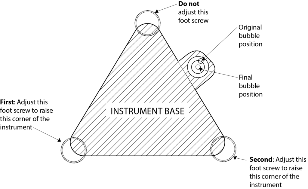
Fish-eye bubbles are always used for getting the instrument roughly level. Adjusting a fish-eye bubble can be frustrating because it is possible to “chase” the bubble around and around the vial until the travel of the foot screws is exhausted. To prevent frustration, choose one foot screw and do not adjust it at all during the levelling process.
Refer to Figure 31. First look at the position of the bubble and adjust the foot screw to raise the corner of the instrument that seems to be opposite the bubble’s position. Then, when the bubble is halfway across the circle, adjust the foot screw to raise the corner of the instrument that is now opposite the bubble’s position. Lastly, adjust the two foot screws to position the bubble. Remember to only adjust two of the three foot screws.
Adjusting a Tilting Level
Tilting levels use a fish-eye bubble with three-pin levelling to get the instrument head level. They also have a secondary eyepiece that, when viewed through, shows the end of a bubble that is split down the middle. When the instrument is sighted on the levelling rod, the operator looks into the split bubble viewfinder and fine-adjusts the bubble using the split-bubble adjustment screw (knob) so that the two ends line up (Figure 32). The telescope is now exactly level in that position, and this process must be repeated every time the telescope is moved to a new site.
Adjusting an Automatic Level
Once the fish-eye bubble in an automatic level is centred, it is rough-levelled, and there are no other adjustments to make. When you look through an automatic level, the light you see passes through a compensator (a prism that is suspended by a number of wires or nylon strands inside a cage). The suspended prism can compensate for the instrument being up to 12° out of level.
The prism completes the fine-tuning for level, and the instrument can be used immediately. If the instrument is lightly shaken before attaching it to the tripod, the prisms and wires will make a faint jangling sound. It is a good idea to check the fish eye from time to time to ensure that the level has not been knocked or bumped out of position, in which case it must be reset. If the automatic level sustains a sharp impact, it may cause the wires or strands to break and the instrument must then be repaired.
Set-up and Operation of Electronic Laser Levels
Select the location for the instrument so that the largest possible area can be covered.
The location should be on solid ground or floor, and out of the way of traffic. Then follow these steps:
- Set up the tripod and attach the instrument. Level the instrument with the levelling screws until the bubble is in the centre circle.
- Connect the power supply to the instrument, and turn the power switch on.
- Using a level rod, establish the height of the instrument from the benchmark.
- Calculate the vertical distance between the instrument and the elevation point you wish to find.
- Attach the sensor or detector to the level rod at this mark.
- If the elevation to be measured is higher than the instrument, hold the rod upside down. If it is lower than the instrument, hold the rod upright.
- Raise or lower the level rod until the sensor indicates the correct level. Mark the end of the level rod at each location where elevations are required.
- An alternative method is to mark the location of the beam directly on the wall, concrete form or column. Then measure up or down the required amount to establish the correct elevations.
Typical Levelling errors
There are many errors that can be made while using an optical level. The following is a list of things that can go wrong, resulting in incorrect measurements:
- Instrument is out of level. The instrument must be level each time a sighting is taken to avoid incorrect rod readings. There are three reasons the instrument could be out of level:
- The instrument was not level to begin with.
- The instrument was accidentally moved between sightings.
- The instrument was set up on an unstable surface, such as soft ground, frozen ground or a wooden floor, and some settlement or movement occurred.
- The rod is incorrectly read. Whenever you take a sighting, say the reading aloud, and then repeat the reading. There is no special way to avoid this sort of error, but taking the reading twice will help.
- The figures on the rod cannot be seen clearly. This can occur if the instrument is set up too far away from the rod. The instrument should be set up about halfway between a benchmark and the location where the reading is to be taken. Equal length backsights and foresights will cancel errors caused by the crosshairs not being in perfect adjustment.
- The instrument is improperly focussed. Make sure the crosshairs are in sharp focus, and the telescope is properly focussed on the rod. Each person’s eyes focus slightly differently, and these adjustments should be made each time you take an instrument out to use it.
- The instrument was levelled using the stadia lines. There are also two other marks on the vertical crosshair called stadia lines. These are used for distance measurement and are not used in levelling. Be careful not to line your eye up with either of these when taking a reading.
- The rod is not held plumb. If the rod is not plumb, the result will be a reading that is a higher number on the rod than the correct reading. The way to avoid this is to give the rod person a signal to slowly pivot the rod forward and backward over the centre point while holding it plumb to the vertical crosshair, and then record the lowest reading.
- The rod person holds the rod at the wrong location or chooses a spot that is not stable. Good communication with the rod person is the best way to avoid this type of error.
Testing the Accuracy of an Optical Level
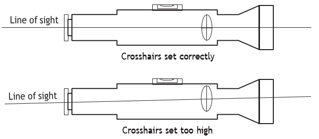
You should always test optical levelling equipment for accuracy before measuring or setting elevations. Even with all of the levelling devices adjusted correctly, the instrument may still not be able to accurately transfer elevations. The cause of error at this point is the accuracy of the crosshair position. The “reticle” that holds the crosshairs can be adjusted up or down and left or right to correctly position the crosshairs in the image.
When you are using the instrument for the first time, its accuracy is not known to you. If the instrument has been bumped or jarred, its accuracy is in question.
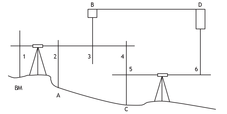
Figure 33 below shows two telescopes set exactly level. The upper telescope has the crosshairs set correctly. The lower telescope has the crosshairs set too high.
The only way to check the position of the crosshairs at the job site is to do a peg test on the instrument.
- Select a location that is reasonably flat alongside a building, or between two buildings, two columns or even two telephone poles. The required distance between locations to use in the test is about 30 m. Figure 34 shows the instrument set-up for checking the level’s accuracy.
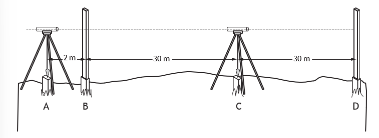
- Set up at location A and level the instrument.
- Have the rod person precisely mark a piece of masking tape stuck to object B (the side of a building or column, etc.) exactly at the line of sight. You will guide this by sighting through the telescope and indicating that the rod person raise or lower the pencil, held horizontally, until it is accurately aligned.
- Have the rod person now move to object D and mark the masking tape located at this point in the same manner as at B.
- Move the instrument to location C and set up as you did before.
- Have the rod person accurately mark the new lines of sight on the masking tape at objects B and D.
- Measure the distance between the marks made on B and D. If they are the same, the instrument is working accurately. If they are not the same, the operation should be repeated. Human nature dictates that errors or inaccuracies are firstly blamed on tools or instruments, so a second check on the readings will eliminate or confirm that as a possibility. If on the second attempt the two differences are not the same, subtract one from the other and divide by 2 to find the error over 30 metres (as the second reading was taken over 60 metres).
Obtaining perfect results is not always practical; a maximum error of 6 mm or [latex]\frac{1}{4} \text{"}[/latex] over 30 metres is usually considered to be acceptable on the peg test.
If the inaccuracy is consistent, the instrument can be checked and sent for repair or to be recalibrated. Adjustment of the crosshairs is done by turning the crosshair adjustment screws. These screws are normally located under a cover just behind the eyepiece. Consult the owner’s manual before trying to adjust the crosshairs or send the instrument to a survey equipment repair shop for adjustment.
Care and Handling of Levelling Equipment
Survey instruments are constructed to give many years of service in adverse weather conditions, but they can be damaged if they are not handled with proper care. Following these rules will ensure that no damage will occur to your instruments:
- During transportation always store the instrument properly in its case. If there is any chance that it will be subjected to jarring, give it further protection by enclosing it in a Styrofoam container.
- When first selecting an instrument, open the lid and carefully look to see how it is secured in its container. You must return it to its container in the same way each time you use it. When it is not in use, you must always return the instrument to its container for storage.
- When protective lens caps are not in use, leave them in the instrument container. Do the same with the thread protector ring and the cap for the tripod, if the tripod has these.
- Before the instrument is mounted on the tripod, make sure that the tripod is firmly set up and all leg adjusting screws and tripod head screws are properly snugged up.
- The mounting head or top plate should be as level to the horizon as you can get it by adjusting the legs.
- If the legs must be positioned on smooth concrete or any other surface where the points of the tripod legs are not able to dig in, use rubber tips or suction cups, or place the tripod in a triangular frame to prevent slipping (Figure 35).
- While transporting the instrument from the case to the tripod, always grasp the instrument by its base, where it should be held to avoid any damage to any of its parts.
- Thread the instrument onto the tripod securely, but do not over tighten. This avoids stripping the threads or putting undue stress on any part of the instrument. This is no time to become distracted. If the instrument is not properly fastened to the tripod and, as a result, falls to the ground and is damaged, time is lost until it is repaired. A loss in both time and money can be avoided if care is taken each time the instrument is set up.
- Never force the instrument while turning it horizontally or while making any adjustments. Forcing it could result in damage. All adjustable features of any level are designed to be just snugged up but never over tightened or forced.
- When the lenses become dusty or dirty, try to wash with water. When doing this, never rub the lens with anything, as this will probably scratch the lens. The best way to clean lenses is to let them dry completely, then use a camel’s hair brush in a circular motion starting at the centre of the lens and working outward. Remember to use the brush lightly and blow out any particles of dirt as you proceed.
- Levels are built to be used in rain and snow but should not be left out needlessly. When you are finished, bring them inside and lightly dry them off (damp dry them), except for the lenses, which should always be left to dry on their own. Secure them in their container but leave it open so that the machine will completely dry. If you close the container the moisture will remain inside to corrode both the instrument and the case (if it is made of metal). Adding a package of desicant such as silicon will help control any small bits of moisture within the case.
- Avoid sudden extreme changes in temperature. If the instrument is kept in storage at room temperature, then taken directly outside into cold or damp conditions, there is a good chance the inner lenses will become fogged. Nothing can be done with it until the temperatures inside and outside the instrument equalize and the moisture trapped within naturally disperses. This can result in loss of time. To avoid this happening, many contractors keep their instruments in locked storage in the same conditions as those in which they will be used or, if properly protected, in their locked vehicle.
- Extreme heat can expand the air bubble in the level vials, making them very difficult to level. To avoid this, put up an umbrella or some sort of sunshade over the instrument.
- Avoid using the instrument where there is a lot of vibration from soil compactors, piledrivers, etc. This could put the level out of alignment, thus requiring repairs.
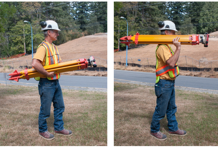
- The way in which an instrument is carried when mounted on its tripod is important (Figure 36). Leave the horizontal clamp loose so that the instrument can swing if it should accidentally hit anything. In wide open spaces, always pack it with the tripod legs in front and over one shoulder. This will help to avoid hitting the instrument, and if you should happen to trip, the tripod should contact the ground before the instrument does.
- If the route you must take is full of obstacles, especially doorways, either pack the tripod- mounted instrument in front of you so you can see what it might come into contact with, or dismantle it and put it in its container.
- Never jar the instrument by banging it down when you are about to set it up, or at any other time. At all times, handle the tool as if it were a crate of eggs.
- Never leave the instrument unattended. There are many ways an unattended instrument can be damaged on a busy construction site. Some contractors paint the legs of the tripod in bright colours and attach streamers of bright surveyor’s tape as a precaution against accidents. Also, the instruments could be stolen if left unattended in an occupied area such as a busy downtown street.
- Check all connections for the various parts of the tripod. Looseness at any of the several connecting points could make it unstable and result in incorrect readings. The wood screw connections of wooden tripods that are subjected to wetting and drying tend to loosen.
Use Levelling Equipment to Establish Elevations
Reading the Levelling Rod
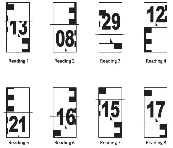
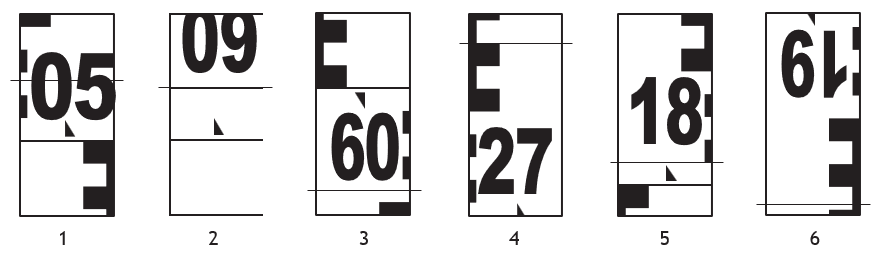
In the metric examples in Figure 37, the triangular black “comma” denotes the metres and decimeters area of the rod seen through the telescope. Reading #1 should be interpreted as 1.330 m; #2’s reading is 0.850 m; #3 is 2.917 m.; reading #4 is 1.185 m. Rod reading #5 should be close to 2.147 m; #6 is 1.625 m; #7 is 1.540 m and #8 is 1.695 m. With a little practice, you should be able to read a metric rod to the nearest 0.001 m.
When reading a rod in imperial measure, first determine whether the rod is in feet and inches or feet and decimals of feet. As mentioned previously, look for the presence or absence of the 11-inch mark.
Figure 38 shows examples of rod readings. The rod is calibrated in feet and hundredths of feet. The footage markings are usually visible in one or two locations between the large numbers representing feet, as shown by the “7” in the lower part of the image.
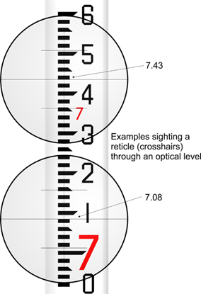
The smaller numbers in black along the right side of the rod indicate decimals of feet, and line up with the pointed end of the black graduations. Each point on this scale represents 0.05′, so there are five graduations between points. This is different from the scales that are in feet and inches. On those scales, the pointed graduations occur every [latex]\frac{1}{2} \text{"}[/latex], so there are only four graduations between points. On the imperial rods, you should be able to read to the nearest 0.005′ or [latex]\frac{1}{16} \text{"}[/latex].
Recording the Readings
The measuring and setting of elevations at a construction site must be done accurately and to the exact specifications shown on the construction drawings. Maintaining a record of how the elevations were set and who set them is also of prime importance. Using a surveyor’s field book to record all instances where elevations were measured or set allows a permanent record of the results to be kept.
The surveyor’s field book is a small, hard-covered book measuring 4 inches by 7 inches. There are many types of field books; the standard field book used for levelling has six columns on each facing page. Some field books have level notes on the left and a grid or graph paper on the right. The grid paper is used to make plan views of horizontal layouts.
Each page in the levelling field book is divided into six columns and 32 rows. The lines on the pages are printed with waterproof ink. When recording instrument readings into the field book, use a pencil, not a pen. The ink from a pen may not be waterproof.
Readings should never be erased once they have been recorded. After a second look, if a reading needs to be changed, cross out the initial reading and put the new reading above it. Leaving the initial reading in the book shows that there was some concern with that reading.
The headings across the top of the pages should always be set up in the same way. Table 1 shows the standard layout of headings.
| STA | BS | HI | IFS | FS | ELEV |
|---|---|---|---|---|---|
Glossary of Levelling Terms
As with any aspect of construction, there are terms, definitions and abbreviations that need to be understood. You should be familiar with the following terms:
Benchmark (BM)
The benchmark is listed first in this glossary because it is the starting point for all levelling. Before any elevation can be measured or set, a benchmark must be found to refer the elevations to. This should be a relatively permanent point of known elevation. It can be any object not likely to move, such as a lamp standard, rim of a manhole or catch basin or a fire hydrant. It is usually noted on the site plan in a set of working drawings. Nothing that is easily moved or shifted should be considered for a benchmark, as it must be used for the duration of the levelling exercise. Residential benchmarks are assigned arbitrary values such as 100.000 m. All parts of the structure are either above this mark and have a higher value, or below this mark and have a lower value.
If benchmarks are given a value relative to mean sea level on the Earth’s surface, they are referred to as datum points. The reason this is the more common way of giving benchmark values is that most structures must tie into existing utilities such as sewer and storm drains, the locations of which are always described with elevations relative to mean sea level. If you have this type of benchmark, it should be very apparent because the altitude of the locality where the structure is to be erected will be known.
Great care must be taken to protect benchmarks from premature demolition or any damage that would spoil their accuracy. Field book records should precisely identify benchmarks so that they can be found again if required when renovations or additions to the structure are made in future.
Backsight (BS)
The first reading of any survey job will be a backsight onto a fixed point of reference, usually a benchmark. The backsight column is just to the right of the (station) “STA” column in the field book. Backsight (“BS”) readings are taken from a levelling rod held plumb on the benchmark or turning point. It is necessary to know the height of the instrument relative to a known elevation, so that work done can be related to that elevation. Therefore, it is a backsight reading that will establish the height of the instrument (“HI”).
Datum
A datum is a clearly defined survey reference marker, from which ground and building levels are measured. This level is referenced to the distance above zero datum, being mean sea level (the average between high and low tide).
Elevations (ELEV)
Elevations are the values assigned to points where elevations have been established relative to the benchmark. These readings are recorded in the “ELEV” column located at the extreme right of the field book.
Foresight (FS)
Foresight readings are taken on points of unknown elevation and are used to determine the elevation of a turning point or the elevation of the final point in a survey. They are essentially the same as intermediate foresights but are listed under their own column so that the math can be more easily checked for errors. FS readings are recorded in the fifth column from the left in the field book.
When determining the unknown elevation, the level rod would be held in a plumb position and the reading from it would be either added to or subtracted from the HI value to obtain the elevation of the turning point relative to the BM.
Height of Instrument (HI)
The height of instrument is the exact elevation of the line of sight of the instrument in relation to the benchmark (BM) or turning point (TP). It is not possible to find the elevation of any point until the height of the instrument is first established, so that is the first step in any levelling exercise. The “HI” column in the field book is the third from the left.
If the line of sight of the instrument is above the BM, then the level rod reading is added to the value assigned to the BM, thus establishing the HI.
If the line of sight of the instrument is below the benchmark, then the level rod reading is subtracted from the BM value to get the HI elevation.
Intermediate Sight (IS) or Intermediate Foresight (IFS)
Intermediate sights are readings taken on all other points of unknown elevation before the last location, which is the foresight or turning point. There is really no practical difference between the foresight and the intermediate sight, except where it is recorded in the field book and how it is used.
Station (STA)
The station is the spot where the rod is being held while a reading is being taken. The station is not where the instrument is set up. In the field book, the station column is the first one on the left side, and it is where sightings (or shots) are identified and their locations recorded. When setting up an instrument, the name of the benchmark used is recorded in this column, as are the names given to points where elevations are established or where unknown elevations are to be calculated.
Turning Point (TP)
A turning point (TP) is set when moving the instrument to a new location. It can be either the last station elevation used or one that can be seen from the new instrument location. The point chosen for the TP must have a prominent point for the levelling rod to rest upon. Once the TP is established, the survey rod is held on it, a foresight reading is taken, and the elevation of the TP is calculated.
The instrument is then moved to the new location and levelled, and a backsight reading is taken on the TP. The levelling rod must be held in exactly the same point on a TP for both the foresight and backsight readings to ensure that the transfer of elevation is accurate. The backsight reading is added to the elevation of the TP to obtain the new elevation of the line of sight.
Example:
Using 100.000 m for the benchmark (BM), a backsight was taken on the BM to determine the height of instrument (HI).
| STA | BS | HI | IFS | FS | ELEV |
|---|---|---|---|---|---|
| BM | 0.527 | 100.527 | 100.000 m | ||
| A | 100.527 | 0.923 | 99.604 | ||
| B | 100.527 | <0.945> | 101.472 | ||
| C | 100.527 | 2.780 | 97.747 | ||
| C | 1.810 | 99.557 | 97.747 | ||
| D | 99.557 | <1.988> | 101.545 |
This height of instrument was used for the next three sightings. As station A is lower than the HI, rod reading #2 is subtracted from the HI to get the elevation for A. As B is above the HI, rod reading #3 is added to the HI.
Station C is a turning point. Once its elevation is determined as 97.747, a backsight from the new location can be taken. By adding the backsight to 97.747, the new height of instrument is found. It is then used with rod reading #6 to find the elevation of station D.
To help protect against errors, inverted readings are enclosed in brackets. The degree of accuracy is also important. Entering 9.42 m instead 9.420 m may lead others to think that measurements where only taken to two decimal places. Showing “m” after the benchmark elevation indicates that measurements are in metres, not feet.
Checking the Math
Total the backsight readings and subtract from that the total of all the foresight readings (not any IS readings). The difference should be the same as the difference between the benchmark elevation and the elevation of the last sight taken. If they differ, the math is out and should be rechecked. If you “close the circuit” (finish back at the benchmark), the two totals should be the same.
Using Instrument Readings
Grading Drains
When grading sanitary and storm drains within a building, the structure itself is normally used as the benchmark or reference for measurements. Using a tape measure, you can measure from the underside of the flooring or joists to the centreline of the piping regardless of whether it is being suspended or installed underground. Grade can be set accurately as long as the flooring or joists are themselves set level, which is usually taken for granted as the norm. However, when piping is to be installed underground outdoors, the only way to do this accurately is by using an optical or laser level and datums. In some cases, such as installing piping from the building to the connection at the property line, you must run your piping at a grade that you must establish in order to meet with the connection at the property line, so there are no changes in elevation due to the use of fittings. In some cases, your piping must be covered and compacted as you install it, so your calculations must be very accurate.
The following examples show the calculations that would need to be performed when grading pipe using elevations that are given in feet and decimals or in metric.
Remember that the relationship between grade, length and total fall, as learned in Level 1 of pipe trades training, is constant and can be expressed three ways:
- Grade × length = total fall
- Total fall ÷ length = grade
- Total fall ÷ grade = length
A tool for remembering these relationships can be a learning triangle (Figure 40).
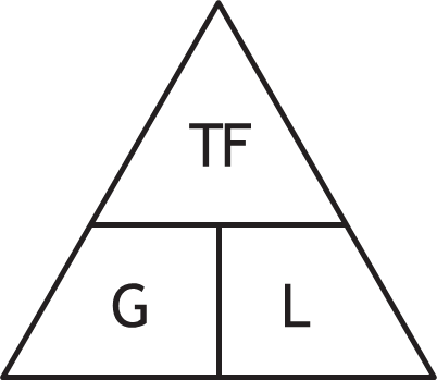
Note: Remember that when grade is in inches per foot, length must be in feet and total fall must be in inches.
Calculating Grade
Example 1: Calculate the grade in inches per foot on the drain in Figure 41.
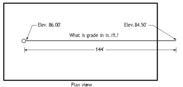
Formula: Grade = total fall ÷ length
Solution: Grade = (86.00′ – 84.50′) ÷ 144′
Grade = 1.5′ ÷ 144′
Grade = 18″ ÷ 144′
Grade = 0.125″/foot
Grade = [latex]\frac{1}{8} \text{"}[/latex]/foot
Calculating Length
Example 2: Calculate the length in feet of the drain shown in Figure 42.
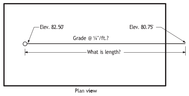
Formula: Length = Total fall ÷ grade
Solution: Length = (82.50′ – 80.75′) ÷ [latex]\frac{1''}{4'}[/latex]
Length = 1.75′ ÷ [latex]\frac{1''}{4'}[/latex]
Length = 21″ × [latex]\frac{4'}{1"}[/latex]
Length = 84′
Note: In the above, express the TF as inches. Also, instead of dividing by a fraction, invert the fraction and use it as a multiplier. That way, the inches in the total fall and in the grade cancel each other out, leaving the only unit of measure in the answer as length in feet.
Calculating Total Fall
Example 3: Calculate the total fall on the drain in Figure 43.
Plan view
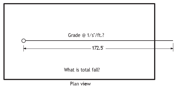
Formula: Total fall = length × grade
Total fall = 172.5′ × [latex]\frac{1''}{8'}[/latex]
Total fall = 21.562″
Total fall = 21 [latex]\frac{9}{16} \text{"}[/latex]
Note: In the above, the feet unit of measurement in the length and in the grade will cancel each other out, leaving inches as the units in the answer.
Example 4: Calculate the elevations at points A and B in Figure 44.
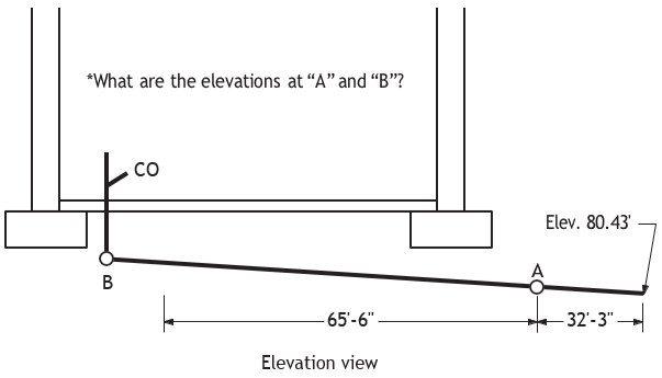
Formula: Total fall = Length × grade
Solution for elevation at A:
Total fall = 32′-3″ × [latex]\frac{1''}{4'}[/latex]
Total fall = 32.25′ × [latex]\frac{1''}{4'}[/latex]
Total fall = 8.062″
Note: The foot units in the length and grade cancel out.
Total fall = 8.062 ÷ 12 = 0.67′
Therefore, elevation at A = 80.43′ + 0.67′ = 81.10′
Solution for elevation at B:
Total fall = (65′-6″ + 32′-3″) × [latex]\frac{1''}{4'}[/latex]
Total fall = (65.5′ + 32.25′) × [latex]\frac{1''}{4'}[/latex]
Total fall = 97.75′ × [latex]\frac{1''}{4'}[/latex]
Total fall = 24.437″
Note: The foot units in the length and grade cancel out.
Total fall = 24.437″ ÷ 12 = 2.04′
Therefore, elevation at B = 80.43′ + 2.04′ = 82.47′
Example 5: Calculate the elevations at stacks A and B in Figure 45.
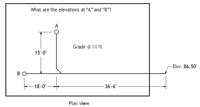
Plan view
Formula: Total fall = length × grade Solution for elevation at A:
Total fall = (36′-6″ + 15′-0″) × [latex]\frac{1''}{8'}[/latex]
Total fall = (36.5′ + 15.0′) × [latex]\frac{1''}{8'}[/latex]
Total fall = 51.5′ × [latex]\frac{1''}{8'}[/latex]
Total fall = 6.4375″
Note: The foot units in the length and grade cancel out.
Total fall = 6.4375 ÷ 12 = 0.54′
Therefore, elevation at A = 86.50′ + 0.54′ = 87.04′
Solution for elevation at B:
Total fall = (36′-6″ + 18′-0″) × [latex]\frac{1''}{8'}[/latex]
Total fall = (36.5′ + 18.0′) × [latex]\frac{1''}{8'}[/latex]
Total fall = 54.5′ × [latex]\frac{1''}{8'}[/latex]
Total fall = 6.8125″
Note: The foot units in the length and grade cancel out.
Total fall = 6.8125 ÷ 12 = 0.57′
Therefore, elevation at B = 86.50′ + 0.57′ = 87.07′
Example 6: Calculate the elevation at stacks A and B in Figure 46.
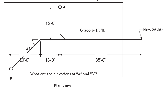
Note: Because the drain from stack B has a 45˚ turn, it is necessary to use the offset formula for 45˚ to calculate the length of travel for the offset. The formula is:
Travel = offset × 1.414
Also note that the Y & [latex]\frac{1}{8}[/latex] bend on the drain from stack A does not add enough extra length above what a sanitary tee would (which is not allowed on a horizontal drain).
Formula: Total fall = length × grade S
solution for elevation at A.
Total fall = (35′-6″ + 15′-0″) × [latex]\frac{1''}{8'}[/latex]
Total fall = (35.5′ + 15.0′) × [latex]\frac{1''}{8'}[/latex]
Total fall = 50.5′ × [latex]\frac{1''}{8'}[/latex]
Total fall = 6.3125″
Note: The foot units in the length and grade cancel out.
Total fall = 6.3125 ÷ 12 = 0.53′
Therefore, elevation at A = 86.50′ + 0.53′ = 87.03′
Solution for elevation at B: Total fall = (35′-6″ + 18′-0″ + travel) × [latex]\frac{1''}{8'}[/latex]
Total fall = (35.5′ + 18.0′ + (20′ × 1.414)) × [latex]\frac{1''}{8'}[/latex]
Total fall = (53.5′ + 28.28′) × [latex]\frac{1''}{8'}[/latex] Total fall = 81.78′ × [latex]\frac{1''}{8'}[/latex]
Total fall = 10.22″
Note: The foot units in the length and grade cancel out.
Total fall = 10.22″ ÷ 12 = 0.85′
Therefore, elevation at B = 86.50′ + 0.85′ = 87.35′
Example 7: Calculate the following using Figure 47:
- Elevations of points A and B
- Depth of the drain at point B below the given datum of 100.00′ expressed in feet and inches to the nearest [latex]\frac{1}{16} \text{"}[/latex]
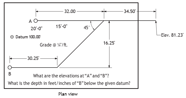
Formula: Total fall = length × grade
Solution for elevation at A: Total fall = (34.5′ + 32.0′) × [latex]\frac{1''}{4'}[/latex]
Total fall = 66.5′ × [latex]\frac{1''}{4'}[/latex]
Total fall = 16.625″
Note: The foot units in the length and grade cancel out.
Total fall = 16.625 ÷ 12 =1.39′
Therefore, elevation at A = 81.23′ + 1.39′ = 82.62′
Solution for elevation at B: Total fall = (34.50′ + travel + 30.25′) × [latex]\frac{1''}{4'}[/latex]
Total fall = (34.50′ + (16.25′ × 1.414) + 30.25′) × [latex]\frac{1''}{4'}[/latex]
Total fall = (34.50′ + 22.98′ + 30.25′) × [latex]\frac{1''}{4'}[/latex]
Total fall = 87.73′ × [latex]\frac{1''}{4'}[/latex]
Total fall = 21.93″
Note: The foot units in the length and grade cancel out.
Total fall = 21.93″ ÷ 12 = 1.83′
Therefore, elevation at B = 81.23′ + 1.83′ = 83.06′
Solution for depth of pipe at B below given datum of 100.00′: 100.00′ – 83.06′ = 16.94′
0.94′ × 12 = 11.28″
0.28″ × 16 = [latex]\frac{4.48}{16}[/latex] = [latex]\frac{4''}{16'}[/latex] = [latex]\frac{1}{4} \text{"}[/latex]
Therefore, the depth below B can be expressed as 16′-11[latex]\frac{1}{4} \text{"}[/latex].
 Self-Test B-1.3: Use Levelling Equipment
Complete Self-Test 1.3 and check your answers.
If you are using a printed copy, please find Self-Test A-1.3 and Answer Key in the Appendix at the end. If you prefer, you can scan the QR code with your digital device to go directly to the interactive Self-Test.

References
BC Industry Training Authority. (2019). Piping trades apprenticeship program: Use Tools and Equipment—Level 1 harmonized [Binder]. Crown Publications, Queen’s Printer for British Columbia. https://www.crownpub.bc.ca/Product/Details/7960000261_S
Camosun College. (2019). Line C: Tools and Equipment—Competency C-1: Describe Common Hand Tools and Their Uses (Rev. ed.) [Learning guide]. BCcampus. https://collection.bccampus.ca/resource/BzEe9fcq/
Camosun College. (2015). Trades Access Common Core Competency C-1: Describe Common Hand Tools and Their Uses. Victoria, B.C.: Crown Publications. Download for free from the B.C. Open Textbook Collection (https://open.bccampus.ca/browse-ourcollection/find-open-textbooks/).
Media Attributions
All figures are sourced from Industry Training Authority (2019) and/or Camosun College (2019) and are used under the Creative Commons Attribution 4.0 (CC BY 4.0) licence unless otherwise noted. Images copyrighted by the BC Industry Training Authority are licensed under a Creative Commons Attribution-NonCommercial-ShareAlike 4.0 (CC BY-NC-SA 4.0) licence.
RIDGID tool images are used with permission from Emerson Professional Tools. Some of these images may have been carried forward from SkilledTradesBC learning resources; however, permission has been obtained directly from Emerson Professional Tools for their use here.
A tool used to check whether a surface or object is perfectly horizontal (level) or vertical (plumb). It helps ensure that structures, pipes, or equipment are installed straight and properly aligned. (Section B-1.3)
A surveying instrument that uses a telescope and leveling system to measure height differences and establish level lines over a distance. It is commonly used in construction and site layout work. (Section B-1.3)
a surveying instrument used in construction to measure height differences and ensure surfaces or structures are level. It usually includes a telescope and leveling screws that allow the user to establish a straight, level reference line across a distance. (Section B-1.3)
A digital measuring tool used to determine whether a surface is level or to measure angles and slopes; uses electronic sensors to detect the position and displays the reading on a digital screen for greater accuracy. (Section B-1.3)
A surveying instrument used to measure horizontal and vertical angles and to establish level lines in construction and layout work. It has a telescope that can rotate both horizontally and vertically for accurate measurements. (Section B-1.3)
A precision surveying instrument used to measure horizontal and vertical angles. It uses a rotating telescope mounted on a base and is commonly used in construction, engineering, and land surveying to establish accurate positions and alignments. (Section B-1.3)
A dumpy level is a basic surveying tool used to measure height differences and check if surfaces are level. It has a short telescope mounted on a base that can be adjusted using screws. (Section B-1.3)
A small, sealed tube filled with liquid and an air bubble. It helps show when a tool or instrument is level. (Section B-1.3)
A measuring tool used to check whether a surface is level (horizontal) or plumb (vertical). It contains small tubes filled with liquid and an air bubble that moves to the center when the surface is straight. Carpenter’s levels are commonly used in construction and carpentry. (Section B-1.3)
A torpedo level is a small, narrow level used to check whether a surface or pipe is level or plumb in tight spaces. (Section B-1.3)
(also known as split-bubble levels or engineer’s levels); a surveying instrument used to measure height differences and establish level lines. It has a telescope that can be slightly tilted to center the bubble in the level vial for accurate readings. (Section B-1.3)
(also known as self-levelling levels); a surveying instrument that automatically adjusts itself to create a level line of sight. It contains an internal compensator that keeps the telescope level even if the instrument is slightly out of position. (Section B-1.3)
A mechanism inside an automatic level that automatically keeps the instrument’s line of sight level. It adjusts the internal optics so accurate readings can be taken even if the instrument is slightly tilted. (Section B-1.3)
Thin horizontal and vertical lines inside the telescope of a surveying instrument. They intersect at the center and are used to aim precisely at a target or measuring rod when taking readings. (Section B-1.3)
Two short horizontal lines located above and below the main crosshair inside the telescope of a surveying instrument. They are used to estimate distance by comparing the spacing between the lines with markings on a measuring rod. (Section B-1.3)
A feature on an optical instrument that allows the telescope or sight to rotate horizontally. It is used to align the instrument with a specific direction or reference point when taking measurements, measuring angles or establishing layout lines. (Section B-1.3)
A permanent reference point with a known elevation used in surveying and leveling. It provides a fixed starting point for measuring the height of other points. (Section B-1.3)
A fixed reference point or level used as a starting point for measuring heights or depths. (Section B-1.3)
A level reading taken on a point with a known elevation, such as a benchmark or turning point. It is used to calculate the height of the instrument before measuring other points. (Section B-1.3)
The starting reference level from which all elevations or depths are measured. It is considered the “zero” point for height measurements. (Section B-1.3)
The height of a point compared to a chosen reference level (datum), such as sea level. (Section B-1.3)
A measurement taken with a level instrument on a point whose elevation is being determined. It is usually the last reading taken before the instrument is moved. (Section B-1.3)
The height of the level instrument’s line of sight above a known point or elevation. It is used to calculate the height of other points. (Section B-1.3)
A level reading taken on a point between the starting point and the final point. It helps measure the height or elevation of different points along the way. (Section B-1.3)
A specific point or location along a line where measurements or readings are taken. (Section B-1.3)
A temporary reference point used when moving a level instrument to a new position. A reading is taken on this point before and after the instrument is moved so measurements stay accurate. (Section B-1.3)