B-1.2 Use Hand Tools
While reading through the material, pay special attention to the safety precautions required when using hand tools.
Use Cutting Tools
Cutting tools have sharp edges that must be well maintained and handled carefully to avoid injury.
Hacksaws
When you attach a hacksaw blade to the frame, be sure the blade is placed on the pins with the arrow on the blade pointing forward, away from the handle. If the arrow is not visible, ensure that the teeth of the blade face forward because all cutting is done on the forward stroke.
There is no such thing as an all-purpose hacksaw blade. The right blade must be chosen for the specific job. The hardness and thickness of the material will determine the blade you should use.
A good rule to remember in choosing the right blade is to be sure that at least three teeth of the blade are in contact with the material being cut at all times. For materials such as wood, it would be recommended to use a 3-10 pitch blade (low TPI) Materials, such as copper may require an 18-24 pitch saw blade (high TPI).
Proper Use of a Hacksaw
Your technique is important when you use a hacksaw because the teeth are extremely fine, and the blade tends to be brittle.
- Be sure the material to be cut is held securely in a vise or C-clamp. Secure the workpiece low in the vise. If the material shifts while you are attempting a cut, the blade may break or the material may be damaged. Be sure that the blade is held tightly in the hacksaw frame to prevent any wandering or warping of the blade during the cutting stroke.
- Never start a cut with the saw held at a sharp angle to the material. This will break or dull the blade’s teeth and also doesn’t allow for at least two teeth contacting the material at all times.
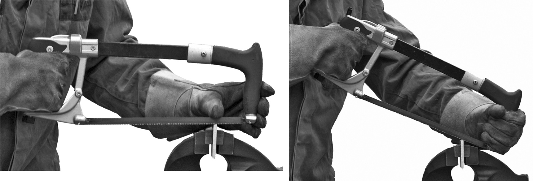
- Grasp the hacksaw securely, with one hand on the grip or handle and one hand on the front of the frame. In starting the cut, guide the blade back toward you with your thumb guiding the side of the blade until the cutting slot is established (repeat this a few times). However, remember that, like a file, a hacksaw cuts only on the forward stroke—drawing the blade back is only done to accomplish a starting kerf.
- Use a little downward pressure on the forward stroke but lift the saw slightly on the return stroke so that the teeth barely touch the material being cut.
- The stroke should be long and steady, employing practically all the teeth on the blade. A lighter pressure should be used on soft metals and thin materials than that used on hard metals and heavier materials. Insufficient pressure on the forward stroke will dull the teeth by rubbing them against the metal without cutting it.
- To ensure the saw blade moves in a straight line, keep your shoulder, elbow and forearm in line with the saw. This alignment is important to avoid any twisting or wobbling of the blade.
- Do not rush when using a hacksaw. Most beginners saw too rapidly. Approximately 60 forward strokes per minute is a maximum. An ideal rate is 40 to 60 forward strokes per minute, with even pressure. If you rush the cut, you may damage the material or create injury to yourself or others.
Wood Handsaws
It is important to select the correct saw based on the direction of grain for the wood you intend to cut.

Using a Crosscut Saw
The following is the procedure for using a crosscut saw:
- Mark the length of the board to be cut.
- Square the line across the board, using a square.
- Hold the saw at 90° to the board and about 45° from the floor.
- Place the saw on the waste side of the line. Half the line should be left. Cutting on the wrong side will make the piece too short.
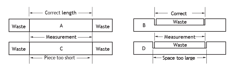
Figure 3 Cutting on the Waste Side of the Line (BC Industry Training Authority, 2019). CC BY-NC-SA 4.0 - Hold the knuckle of your thumb against the side of the blade. This helps to guide the first few strokes when you start a cut.
- Start the cut gently and follow the line.
- As you cut, keep your shoulder, elbow and wrist in line with the back of the saw blade.
- Do not exert more pressure than you need. If too much is used, the saw may buckle, jump, and cut the operator’s hand.
- Use the full length of the blade to make the cut. Do not force the saw. Make long, smooth cuts.
- Support the waste stock near the end of the cut. Slow down and shorten the length of the stroke. This prevents splitting the wood.
Using a Ripsaw
Using a ripsaw is similar to using a crosscut saw, except that the larger teeth can cause the saw to buckle more easily. As well, the wood may tend to bind the saw even though the saw has a good set.
The cause lies in the wood itself. When wood is split lengthwise, some of the tensions inside are released, and those remaining in the wood may make the edges want to move toward or away from each other. If the wood binds the saw in a cut, place a wedge at the start of the cut and move it as necessary.
Files
Different kinds of files are used to get the best results with different types of metal. All files are classified in two ways; by shape and by cutting face.
Shapes
The two commonly used shapes of files are the flat file and the half-round file.
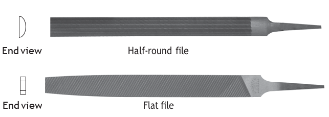
The half-round file is used in pipe welding when putting the landing on the pipe and for removing slag and burrs. The flat file tapers at the point and generally has teeth on both edges. Flat files are used for general-purpose filing and for draw filing.
Cutting Faces
Remember that cutting faces are classified according to the design of the cutting and according to the grade of their teeth. There are three designs of cutting face, the single-cut, the double-cut and the curved tooth.
These were covered in detail in Learning Task 1: Files.
File Handles
Files are sold without handles, so the first step in using a file is to fit it with the proper handle. Always select a handle that fits the file, neither too large nor too small for the file tang. File handles should have a strong ferrule, or metal collar.
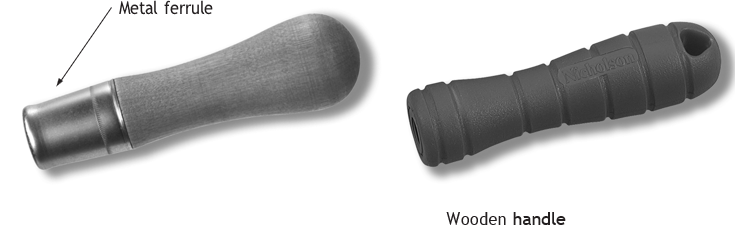
There are two excellent reasons for using a file handle on all files. The first and most important is your safety. The tang of a file is usually pointed. If you meet an obstruction while filing and the file stops suddenly, your hand could be severely punctured. Second, the handle helps guide the file and the work can be done more accurately and more quickly.
Filing Technique
If you are new to working with files, take your time and check your work frequently in order to do the job correctly. Some very common mistakes are:
- Rocking the file from left to right as the material is being filed. This will create a curved rather than a flat surface.
- Bearing down too hard in the middle of long cuts, thereby creating a dip in the middle of the material.
- Filing for too long without checking the material. Frequent checks will help you detect incorrect filing methods and prevent you from removing too much material.
- Filing with arm movement only. Your body should lean forward slightly during the forward stroke, then return to an upright position during the backward stroke.
Your workpiece should be placed in a bench vise. If it is a soft material such as aluminum, you should protect the workpiece by placing pieces of wood, plastic or soft metal between the vise jaws and the workpiece. Always wear eye protection during filing operations.
When moving the file across any work, hold the file as shown and move it straight ahead or at a slight angle. Hold it so that the handle end fits into the heel of your hand, with your thumb lying along the side of the file. Your forearm and the file should form a straight line.
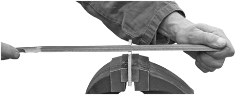
Hold the point of the file with your thumb and first two fingers of the other hand. For heavy filing strokes, the whole underside of your thumb should press down. On lighter strokes, place your thumb more at a right angle to the file.
When filing a piece of material, frequently stop and check your work for even cutting and squareness. If you are filing incorrectly or at the wrong angle, you will discover the problem before the material has been ruined.
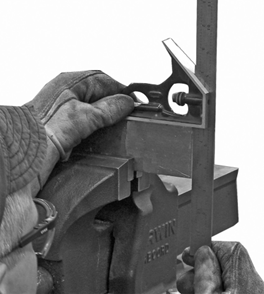
An accurate method of checking your work for even cutting is by using a steel square. Hold the body of the square firmly against one edge of the material and check that no clearance is visible between the bottom of the blade and the top edge of the material. If clearance is visible, your filing methods are incorrect.
Draw Filing
Draw filing is used to finish a smooth surface by removing only small amounts of material at a time. Generally, a single-cut file is used for this operation. When filing pipe however, it may be preferable to use a double-cut file.
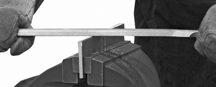
To draw file, hold the file in both hands with your thumbs approximately 13 mm to 38 mm ([latex]\frac{1}{2}[/latex] in. to 1[latex]\frac{1}{2}[/latex] in.) from each side of the material being cut. Then either push or pull the file straight across.
Raise the file slightly on the backstroke, as with ordinary filing. In the case of such soft metals as aluminum, brass, copper or lead, you can apply pressure on the backstroke without damaging the file.
With different grades of files, the angle at which the file is moved across the material will vary slightly, depending on the type of material being cut.
Maintenance of Files
Before starting any filing operation, especially the filing of mild steel or soft non-ferrous metals, coat the file with chalk. The chalk acts as a dry lubricant and prevents metal cuttings from becoming pinned or trapped in the teeth of the file.
Metal particles trapped in the teeth of a file not only reduce the file’s ability to remove metal from the workpiece but may also cause damage to the surface of the workpiece.
As soon as you notice a build-up of particles on your file, brush them off with a file card. A file card has wire bristles on one side and fibre bristles on the other.

Begin cleaning the file with the fibre bristles. If particles remain, remove them with the wire bristles.
Sometimes after filing soft metals such as aluminum, copper and lead, filings will remain stuck between the teeth even after you have used the file card. If this happens you should use a sharp, pointed piece of hard wood or soft iron to pick the remaining filings from between the teeth.
Never use a piece of hardened steel (such as a pointed punch or chisel) to pick file teeth clean as the tempered steel can damage the teeth.
Storing Files
More files wear out from abuse than from use. To maintain files while they are not being used, keep them separated from each other and from other tools to prevent damage to the file teeth.
A simple method for safely carrying your files in a tool box (or any place for that matter) is to fold a piece of cardboard into an accordion shape. Each fold should be just wide enough to entirely cover the file blade. Place a file in each fold of the cardboard and fold the accordion together. Use heavy elastics or strips of inner-tubing to secure the file compartment.
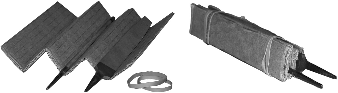
Once your files have been securely wrapped, always store them in a dry place. Rust will adversely affect the cutting edge of file teeth.
Chisels
Select the appropriate chisel for the material being cut.
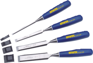
Cutting with Wood Chisels
Almost all wood chisels should be driven with a wooden mallet. The exception is the framing chisel, which can be driven with a steel hammer. All work should be held firmly in place, either in a vise or with a bench hook. All cuts should be with the grain of the wood, not against the grain. The blade should be angled for a slicing action instead of cutting square across.
Keep both hands back of the cutting edge. Do not cut toward yourself; always cut away from yourself. Never hold the work in one hand and the chisel with your other hand. Never chisel toward another person. Wear safety glasses when making heavy cuts with a hammer. Keep the chisel sharp at all times.
Cutting With Cold Chisels
Cutting with a cold chisel is a quick and efficient method of removing surplus metal on mild steel up to 3 mm ([latex]\frac{1}{8}[/latex] in.) thick. In this type of cutting the workpiece is held in a vise, and the metal is sheared between the sharpened edge of the chisel and the edge of the stationary jaw of the vise.
It is important that the chisel be held correctly; otherwise, a rough or badly twisted job will result, and both the chisel and vise may be damaged. The bottom face of the chisel should be flat against the jaw of the vise, and the chisel must be angled to achieve a clean shearing action.
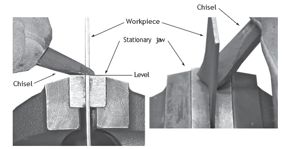
Never try to cut from the end of the metal, as illustrated.

You can control the depth of the cut by raising or lowering the angle of the chisel. As you approach the end of a cut, strike the chisel lightly because a hard blow could cause the metal to fly off and injure someone nearby.
If you are right-handed, you should hold the chisel in your left hand and use your right hand to swing the hammer, or your left hand, if you are left-handed.
Never grip the chisel too tightly. A poorly aimed blow that misses the chisel could seriously injure your hand.

A note about PPE: Always wear goggles or a face shield when you are using a chisel!
Always select a chisel large enough to do the required job. Chisels are usually struck with a hammer that weighs from 340 g to 900 g (3/4 lb. to 2 lbs.). A large hammer should be used with a large chisel.
Inspection, Maintenance and Storage of Chisels
Regularly inspect chisels for damage. Common conditions are shown here. The head of the damaged chisel, as compared to the undamaged chisel as shown has become mushroomed and the cutting edge has become nicked and dull with prolonged use. When this happens, the chisel must be dressed (cleaned up or repaired) before it can be used again. Mushroomed heads can be extremely hazardous.
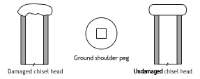
Five basic rules for dressing chisels:
- The tool must be returned to its original shape. Check an undamaged tool to determine the original shape.
- All cracks and spalls (chipped areas) must be removed. Some cracks cannot be seen with the naked eye. If possible, use a magnifying glass for a closer look.
- The grinding temperature must be kept low. The material should not turn yellow or a blue/purple colour. If the grinding temperature is not controlled, the hardness of the area that is being ground can be lost, making it hard, brittle and easily fractured. Generally, chisels are heat-treated (hardened) approximately 38 mm (1[latex]\frac{1}{2}[/latex] in.) back from the cutting edge. The grinding of the chisel should be kept well within these areas.
- A medium or fine grit grinding wheel should be used.
- The wheel rotation should always be away from the cutting edge, toward the body of the tool. This positioning of the tool directs heat away from the cutting edge.
When a tool has been damaged and redressed many times, it loses many of its original qualities and becomes unsafe.
Always store a chisel in a dry tool box or wrapped in a clean, dry rag. Protect the edge from damage; often manufacturers supply a protective cap to keep the chisel’s edge, which is ideal.
Pipe Cutters
The following procedures for using different types of pipe cutters are general. In actual practice, you may find it difficult to follow these steps exactly. You should, however, aim to follow them as closely as possible.
Procedure for Cutting Steel Pipe
The following procedure describes cutting steel pipe:
- Set the piece of pipe to be cut in a vise on a workbench or tri-stand.
- Ensure the pipe end rests level in the vise. If necessary, use a pipe support stand to keep the pipe level and properly aligned.
- Measure and mark the pipe to the desired length. (Use pencil, chalk or soapstone.)
- Secure the pipe in the vise. The jaws of the vise should grip the pipe firmly, but not to the point where the teeth of the jaws dig excessively into the pipe. Too much pressure will result in a deformed, out-of-round pipe.
- Select the correct type of cutter for the job. Inspect the cutter wheel to make sure it is:
-
- Not damaged
- Sharp
- Designed both for the cutter and the material to be cut
- Open the cutter jaws by turning the feed handle. Place the cutter on the pipe so that the rollers are in contact with the pipe.

It is important that the cutter rollers are against the pipe before you begin the cut. This ensures that the cutter will remain steady and square during the cutting operation.
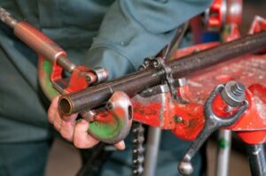
- Turn the screw handle until the cutter wheel touches the pipe. Then gently engage the cutter wheel by turning the feed screw one-quarter of a turn.
- Rotate the cutter a full 360° around the pipe so that the cutter wheel cuts a light groove.
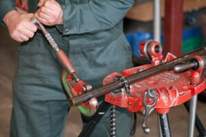
- Check the groove to see if it tracks into the original starting groove. If it tracks, you will have a good cut. If it does not, the result will be a spiral groove on the pipe, not a cut.
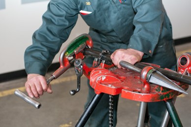
- When a true track is obtained, tighten the feed screw one-quarter of a turn and rotate the cutter around the pipe. Continue to tighten the feed screw at each turn until the pipe is cut.
As well as steadying the cutter, the rollers “roll down” the burrs that the cutter wheel creates on the outside of the pipe.
Procedure for Cutting Copper Tube
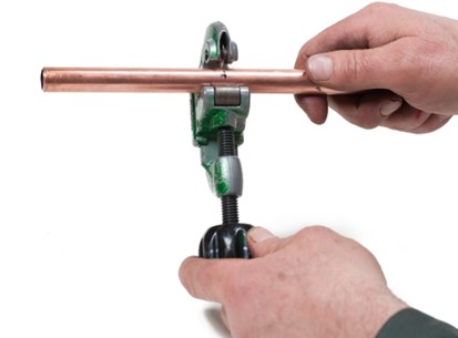
The procedure for cutting copper tubing is similar to that of cutting steel pipe. Here are a few of the differences:
- Some tubing cutters use a screw to anchor the rollers to the body of the cutters. When using these types of cutters, the rotation of the cut must be correct to ensure that the roller screw does not loosen and eventually fall out. Often, it is better to allow the handle of the cutter to lead the cut. Check the tension on any adjustable parts regularly.
- When measuring tubing, it can sometimes be advantageous to quickly score the tubing at the required length with the back of a blade reamer (if the cutter being used is equipped with one), instead of using a marking pen each time. This can save a lot of time when taking multiple measurements.
Maintenance of Pipe Cutters
Follow these guidelines to ensure safe operation and a long life for pipe cutters:
- Periodically use a cleaning solution and a wire brush to clean the main parts of the cutter: the feed screw, the slide, the rollers and the cutter wheels.
- Use a suitable lubricating oil to thoroughly lubricate the feed screw, the slide, the rollers, and the cutter wheels. (Do not use thread cutting oil.)
- Inspect the cutter body, the feed screw, and the rollers for damage. Examine the tool for true tracking and sharpness of the cutter wheels. Replace any worn or damaged part of the tool, including the cutter wheels.
- Hang the cutters in a dry, warm place, if possible.
Using a Soil Pipe Cutter (scissor and ratchet)
No vise is required for cutting soil pipe, as cutting is usually done on the ground or on the shop floor.
- Measure and mark the pipe to the length desired using chalk or soapstone.
- Position the cutter on the mark.
- Wrap the cutter’s chain around the pipe. Tighten the chain using the hand wheel adjuster (Make sure the cutting chain is at right angles to the pipe.)
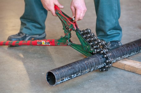
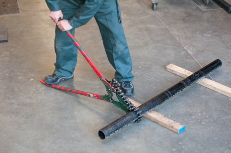
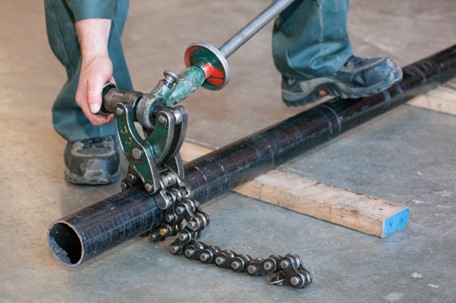
- Pump the ratchet handle of the cutter until the pipe separates. If using the squeeze handle (scissor) type, squeeze the handles until the pipe separates.
Procedure for Cutting Glass Pipe (Internal Cutter)
The following procedure describes use of an internal glass pipe cutter:
- Measure length of pipe required and mark glass with a pencil, grease crayon or felt marker.
- Insert cutter head into pipe with the cutter wheel facing up.
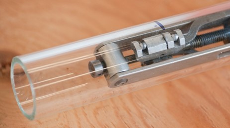
- Slide the centring cone into the pipe until it seats against either the cut or beaded end.
- Slide position collar against cone, align cutter wheel with distance mark on pipe and then lock ring stop using positioning thumb screw.
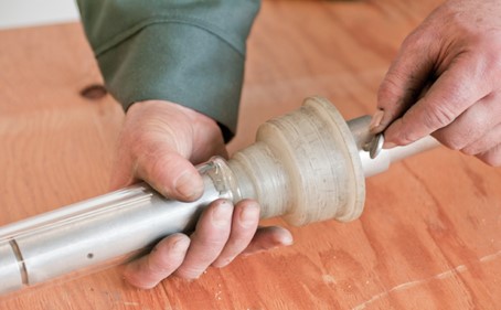
- Turn tension adjustment knob clockwise until cutter wheel contacts glass. Double check alignment of cutter wheel with mark on pipe. Note that the follower wheel does not assist in the scoring of the pipe, but it is required to assist in tensioning the cutter head.
- Continue to turn tension knob clockwise to give sufficient pressure on cutting wheel to score the glass (a medium to light score is desirable on 1[latex]\frac{1}{2}[/latex] in. to 3 in. pipe; use a heavy score on 4 in. pipe and larger).
- With pipe firmly pressed against centring cone (and cone against position collar), make a test score about 4 mm ([latex]\frac{1}{4}[/latex] in.) long. Make final adjustments to tension knob, if required.
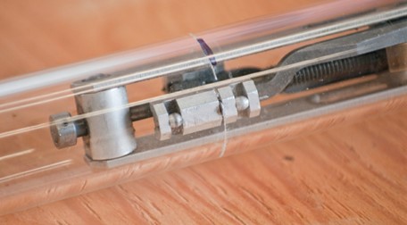
- Complete score around pipe by turning shaft one complete revolution—avoid scoring beyond the closing point of the circle of the cut.
- Turn the tension knob counter-clockwise to draw the cutter wheel away from the inside wall of the pipe. DO NOT drag the scoring wheel against the pipe when removing the cutter.
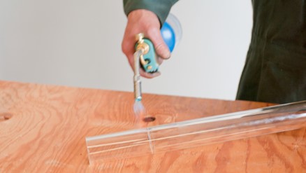
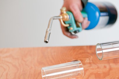
- Apply heat from a torch on score mark. As pipe begins to separate, follow score mark with flame. It may be necessary to tap the piece slightly to assist in separation of the two halves.
- A plain-end coupling can now be used to transition the cut piece of pipe to a beaded fitting, a factory-beaded pipe, or another plain-cut end of pipe.
Reamers
As you learned in Section B-1.1, reamers are used for deburring the inside of cut pipe to allow for full fluid flow. Reamers are made for pipe sizes from 3 mm to 10 cm ([latex]\frac{1}{8}[/latex] in. to 4 in.).
When using a reamer, the burr is only to the full bore of the pipe. Do not make the pipe wall thinner than it was manufactured.
To use either type of reamer as a hand tool, a ratchet handle is inserted onto the unit. To start the operation, centre and rotate the reamer slowly to allow it to align with the pipe’s bore. Next, use the ratchet handle to apply pressure to the flutes and to turn the tool clockwise. The feed should be steady and rapid.
Pull back on the handle to remove the reamer. Inspect the interior pipe wall visually to determine if the burr has been removed.
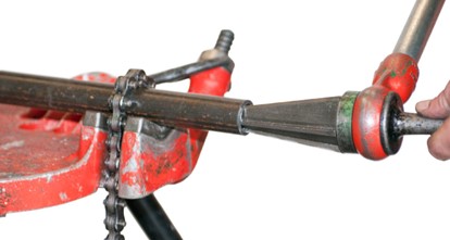
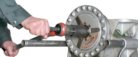
Hand reamers can be used in conjunction with power vises, as seen below.
Never use a spiral hand reamer with a power vise, because it bites deep, and can jam.
Maintaining Reamers
Follow these guidelines to ensure safe operation and a long life for the reamer:
- Clean the flutes of the reamer with a cloth or a wire brush.
- Inspect the edges and the grip for damage. If the flutes need regrinding, set the tool aside for professional repair.
- From time to time, feed lubricating oil into the ratchet mechanism in the handle.
- Store the reamer either in a toolbox or by hanging it up so that the flutes will not be damaged.
Chalk Lines
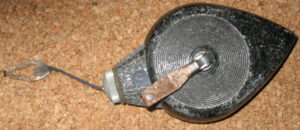
On a flat surface, a line can be marked using powdered chalk on a cotton cord. When the cord is “snapped” on the work surface, a dusting of chalk is left. Coloured or white chalk can be used.
The chalk line is fitted around a reel housed in a case. The powdered chalk is put into the case by removing a cap on the top face of the case. A metal ring with a hook is attached to the end of the line. The hook can be hooked over the end of a board or panel or onto a nail inserted for that purpose.
To use the chalk line, do the following:
- On the work, mark the two points between which you want the line to be located.
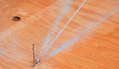
- Hook the ring over a nail or the end of the work, at the point where you want the line to start.
- Pull the line horizontally out of the case, but do not allow it to touch the work.
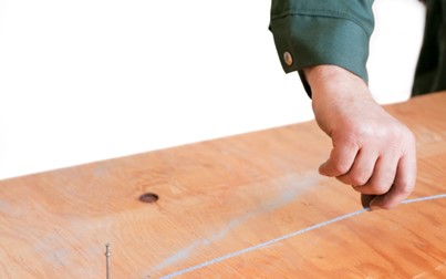
- Pull the line tight and place the end on the mark or past the point to be snapped.
- With your other hand, lift the line straight up, about 100 to 150 mm; then allow it to snap down and a chalk mark will be left on the work.
The following are other pointers on the use of a chalk line:
- If the line to be marked is very long, ask a fellow worker to hold down the line at the centre point, then snap the line on either side.
- When you chalk a line on a vertical surface, the line may sag. If so, use a nail to raise and support the line and ask a fellow worker to sight along the line to make sure it is straight.
- When the chalk line begins to fade, add more chalk powder to the case.
- Too much chalk in the case leaves a fuzzy line.
- Many chalk line tools have a shape that allows them to be suspended by their cord, thereby acting as a plumb bob.
- Some models have locking and quick release mechanisms as well as quick retrieve gear ratios to make them easier and quicker to use.
Wrap-around
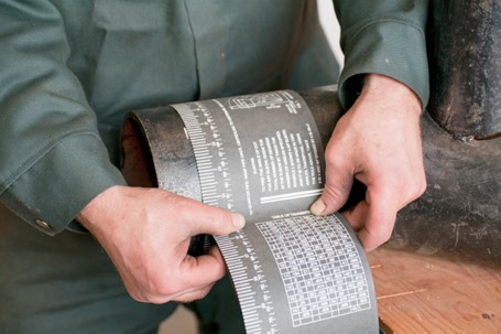
When you have determined the length that a pipe is to be cut, a wrap-around can be used to make a straight, clean line around the pipe’s circumference. This is especially beneficial if you aren’t using a set of rotary cutters, but rather a high-speed cutting disk or an oxyacetylene cutting torch.
The following is a procedure for using the wrap-around:
- Remove any varnish from the coating of steel pipe with a wire brush or a grinder equipped with a high-speed wire wheel.
- Start by looping one end of the wrap-around around the pipe to one side of the mark and line up the edge of the short running end with edge of the longer rolled end.
- Hold it snuggly between your hands as you slide it toward the mark on the pipe.
- Holding the wrap tightly to the pipe, carefully tuck the short end on to the pipe and wrap the long end at least 1[latex]\frac{1}{4}[/latex] times around the pipe in an over-lapping fashion.
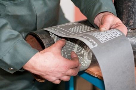
- With the wrap-around tightly in place, draw a line with a sharp piece of soapstone around the pipe, using the boundary of the wrap as a straight edge.
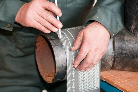
Hammers
Using a hammer correctly is important for reasons of safety. When using a hammer in conjunction with tools such as a cold chisel, incorrect usage could result in the cold chisel becoming a dangerous projectile.
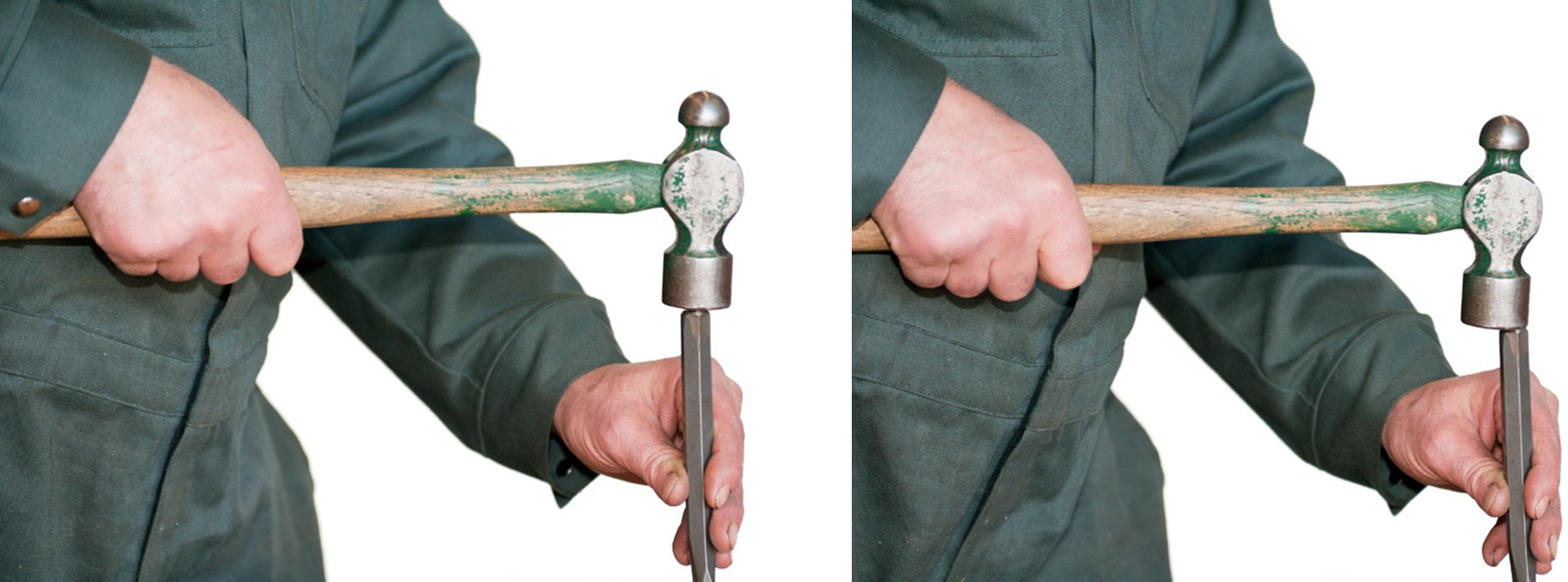
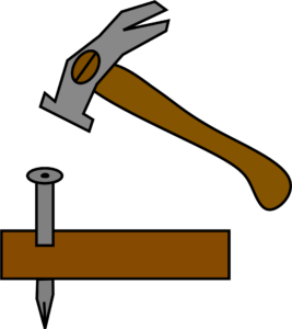
The correct way to hold and use a hammer is illustrated below. To strike a heavy blow with the least effort, grip the hammer firmly, but not rigidly, near the end of the handle. Gripping the handle near the head reduces the force of the blow. Always strike the object with the centre of the face of the hammer. That way, you will protect the face edge from chipping as the blow is distributed over a larger area. All hammering should be started with light blows, followed by heavy blows, if necessary.
General Rules for Nailing Wood
Nail thinner pieces of wood to thicker pieces of wood. This provides more holding power. Stagger the nails so that they are not in line with the grain of the wood (to prevent splitting).
Do not drive nails too close to the edge of the wood. Keep them back a minimum of 20 mm, or a distance equal to the thickness of the material, whichever is less.
If the wood is very hard, and you encounter difficulty in driving nails, or if the wood is very narrow and tends to split, drill pilot holes that are slightly smaller than the nails being used.
Place the chisel point of the nail across the grain so that it will cut the wood fibres as it is driven in.
When nailing into the end grain of wood, drive the nails at an angle to provide more holding power. Provide solid support for the members. Members without proper support tend to bounce and cause nailing problems.
Do not use a hammer to strike the face of another hammer. This could cause a fragment of hardened steel to fly off and injure the operator or others. Use a small pry bar or nail puller to pull hard-to-remove nails.
Always wear eye protection equipment when using a hammer. Never use a hammer that has a loose head or a damaged handle. Injury can result if the head flies off or if the handle breaks.
Follow these guidelines to ensure safe operation and a long life of hammers:
- Keep your hammer clean at all times. A greasy or dirty hammer can be dangerous.
- Always use a hammer of the correct size and weight for the job.
- Never strike an object with the side of a hammer.
- Never strike hardened steel objects with a hammer, as this may cause chips to fly.
- Use wire brush to clean textured face.
- Regularly inspect handle for damage.
Vises
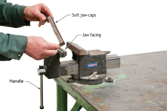
To use a vise, simply rotate the handle to the desired opening. Place the work piece in the vise and tighten it just enough to hold it in place. If the part being held is soft or brittle, it may be broken or compressed by too much pressure.
Soft vise jaw-caps are available to protect the workpiece. They come in pairs and slip over the jaw facings. The tabs are bent around the front and back jaws to hold them in place.
Know the type of material being clamped in the vise. Be sure the jaw facings are of the type that will not damage the material. If jaw-caps are not available, use two strips of aluminum, copper, brass or wood to protect the material.
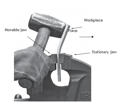
For a hard or tough work piece that is to be hammered or chiselled, you must ensure that the vise is tight enough to prevent the workpiece from slipping. You should also place the workpiece in such a position that you will be hammering or chiselling toward the stationary jaw.
Never hammer on the vise unless there is an anvil built on the vise for that purpose. Remove the screw periodically for cleaning and lubrication. When the jaw facings wear out or lose their gripping power, replace them. Never over-tighten the vise handle by using an extension bar over the handle ends or by hammering on the handle.
Follow these guidelines to ensure safe operation and a long life for the vise:
- Clean the housing of the vise with a solvent as the need arises.
- After using the vise, clean the gripping surfaces with a wire brush.
- Use a good grade of lubricating oil to clean and lubricate the screw spindles and any hinged joint.
- Inspect the gripping devices for damage or excessive wear, and replace if necessary.
- Keep the surfaces of the vise and work area free of grease, dirt, and other tools.
- If the vise is portable, hang it up in a clean, dry area when it is not in use.
Wrenches
Keep your wrenches clean. Working with greasy, dirty tools can be dangerous, as your hands can slip, causing injury. The dirt can also damage the component on which you are working. Adjustable wrenches and pipe wrenches should be cleaned and lightly oiled periodically.
Make sure the wrench is the correct size for the job. Loose-fitting wrenches can damage both the workpiece and the jaws of the wrench.
Do not abuse the wrench by driving on it with a hammer or by adding leverage with a piece of pipe. Do not use any wrench as a hammer and do not use socket handles for any purpose other than driving sockets. Do not use a socket wrench as a bushing or seal driver or for any other purpose. Check socket wrenches for chipping and cracking or other damage. Do not use them if they are damaged.
Hex key wrenches can be reconditioned if the end of the key becomes worn and slips in the socket head screw. Grind the end back to a point where the hexagon shape is true. Be careful that you keep the tool cool during the grinding operation to avoid affecting the hardened metal.
Pipe Wrenches
The following procedure describes the use of pipe wrenches:
- Select the correct wrench type and size for the job. (A loose-fitting wrench will slip and very possibly cause hand injuries.) A pipe wrench is designed for round stock. It should never be used on square or hexagonal material. The following list shows the correct pipe wrench to use for various common pipe sizes:
| Wrench size (inches) | Pipe size (inches) |
| 8 | [latex]\frac{1}{8}[/latex] and [latex]\frac{1}{4}[/latex] |
| 10 | [latex]\frac{3}{8}[/latex] and [latex]\frac{1}{2}[/latex] |
| 14 | [latex]\frac{3}{4}[/latex] and 1 |
| 18 | [latex]1\frac{1}{4}[/latex] and [latex]1\frac{1}{2}[/latex] |
| 24 | [latex]2[/latex] |
- Inspect the wrench for damage. Jaws that are sprung or teeth that are dull, for example, can cause the tool to slip.
- Mount the pipe wrench correctly on the work piece. Regardless of the size of the wrench, there must be a gap between the shank of the hook jaw and the pipe. This permits the pressure of the two gripping surfaces (the heel jaw and the teeth of the hook jaw) to firmly grip the pipe for full turning force.
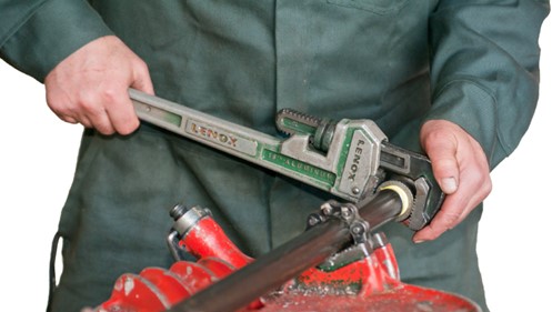
- With a grip on the pipe, push or pull on the wrench in the direction it is intended to move.
- To obtain a new grip on the pipe, move the handle in the reverse direction. This will release the workpiece, and the handle can then be moved to its original position and a new grip obtained. Follow this procedure until the workpiece has been given as many turns as required.
- Do not use a wrench to lift or bend pipe.
- Do not use a substitute device or “cheater” to increase the leverage of a wrench.
- Valves, regulators and controls are not designed to withstand the torque across their body that is necessary to tighten or loosen them. Grasp the valve on the same end as the pipe on which you are working.
- Never grasp the open end of a fitting with a wrench. A pipe, nipple or adapter screwed in a few turns will prevent bending the open end of the fitting.
Maintaining the Condition of Pipe Wrenches
Follow these guidelines to ensure safe operation and a long life for the pipe wrenches:
- To prevent rust, apply oil at regular intervals to nuts, springs, jaws and other moving parts.
- Inspect the wrench before and after use for worn or broken parts. Pay particular attention to the heel and hook jaw or clasping device. If the teeth are worn, the wrench can sometimes be restored to usefulness by filing the teeth with a triangular file.
- Store the wrench properly. Use the hole in the handle to hang it up or hang it in a slotted holder designed for tools.
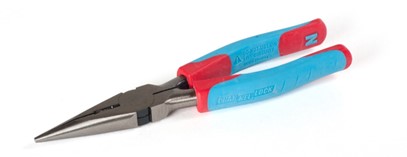
Pliers
When using pliers, observe the following:
- Pliers are not made to withstand any pressure in excess of normal hand squeezing.
- Never attempt to cut large screws or bolts with a pair of cutting pliers.
- Never put excessive side pressure on needle-nose pliers.
- Never expose pliers to a direct flame.
- Do not use pliers on nut or bolt heads.
- Wear safety glasses when cutting wire.
- Cut at right angles.
- Use the right tool for the job.
Screwdrivers
Screwdrivers should be kept clean and free of grease, oil and dirt. The handle should be intact and well secured, and the tip should not be worn. When a tip becomes worn, the slot screwdriver can be filed to shape, but other types must be replaced.
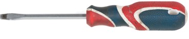
Screwdrivers should never be used as prying tools, punches, hammers or chisels.
Tubing Spring Benders
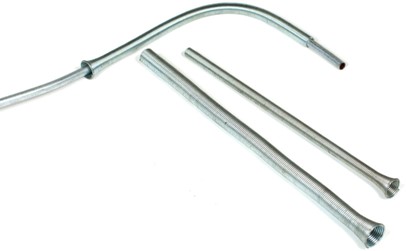
The following procedure describes using tubing spring benders:
- Select bending spring that just fits over the tube to be bent.
- Slip the centre of the spring over the centre of the area to be bent.
- Hold bender in both hands, with thumbs supporting the back of the curve and slowly make the bend.
- Grasp flanged end of the spring and remove from the tubing.
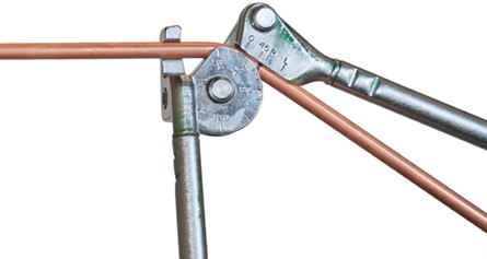
Tubing Compression Hand Benders
The following procedure describes using a compression hand bender to form a 90-degree bend:
- Measure tubing to the desired length at the centre of the 90° bend. Mark all the way around the tube with a pencil or felt marker. (If more than one bend is required on the tube, measure from the centre of the previously completed bend to the centre of the new bend to be formed.)
- Place the tubing in the bender with the measured end of the tubing along the stationary handle of the bender. (The critical measurement is to the left of the mark.)
- Position the measured mark directly in line with either the 90 or L notch on the placement link (manufactures vary in their design). Secure the tubing fastener onto the tube (making sure the 0 notch on the bending wheel and placement link are in line).
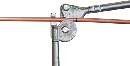
- While moving the pull handle toward the stationary handle, pull down smoothly and evenly until the 0 notch on the placement link lines up with the 90° mark on the bending wheel.
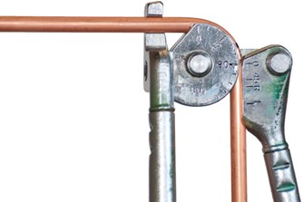
90-Degree Reverse-bend
The R indicator notch on the placement link is used when the end of the tube from which the dimension is measured is reversed from what is described above. (In other words, the critical measurement is to the right of the bender.)
45-Degree Bend
The following procedure describes using a compression hand bender to form a 90-degree bend:
- Measure tubing to the desired length at the centre of the 45° bend. Mark all the way around the tube with a pencil or felt marker. (If more than one bend is required on the tube, measure from the centre of the previously completed bend to the centre of the new bend to be formed.)
- Tubing can be placed in either direction from the bending wheel.
- Position the measured mark directly in line with the 45 notch on the placement link. Secure the tubing fastener onto the tube (making sure the 0 notch on the bending wheel and placement link are in line).
- While moving the pull handle toward the stationary handle, pull down smoothly and evenly until the 0 notch on the placement link lines up with the 45° mark on the bending wheel.
Tubing Gain (Bend Length Increase)
When bending tubing, the actual bend made does not follow the absolute profile of a straight line layout. Realistically, the bend made in a tube will short-cut the angle slightly on each bend.
This short-cutting of the corners gives “additional length” to the remaining section of straight tube.
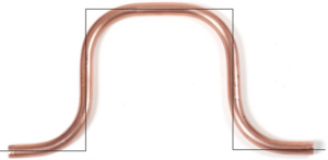
The additional length is commonly referred to as gain.
Gain for 90-degree bends is approximately equal to the OD of the tube being bent. Tables are available that provide the exact gain lengths for various sizes of tube and different bending radii.
If bending is performed correctly by proper positioning of the measurement mark on the placement link (and in multi-bending operations, measuring each bend from the previous bend), the gain will appear correctly on the straight length of the tube opposite the measured length.
Bending in this manner will ensure correct end-to-centre and centre-to-centre measurements when bending tubing.
Flaring Tools
Tube flaring is a method of forming the end of a tube into a funnel shape so it can be held by a threaded fitting. When a flared tube is prepared, a flare nut is slipped onto the tube, and the end of the tube is flared.
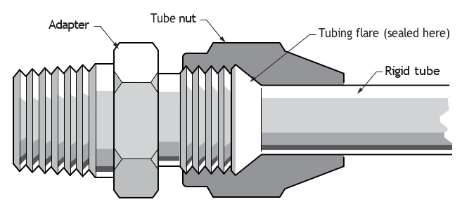
During tube installation, the flare is seated to a fitting with the inside of the flare against the cone- shaped end of the fitting, and the flare nut is screwed onto the fitting, pulling the inside of the flare against the seating surface of the fitting.
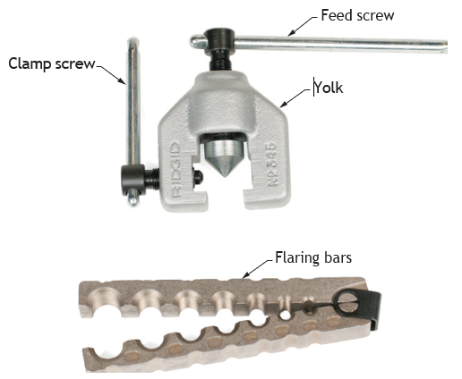
The following procedure describes the use of a flaring tool:
- Cut and ream tubing.
- Slide flare nut over tubing.
- Back off feed screw handle and clamp screw to permit flaring bars to slide freely through the yoke. Slide yoke to the hinged end of the flaring bars.
- Insert tube into proper size opening and close flaring bars. Push tube up from bottom of the tool until it is even with top of flaring bars.
Note: Oversize or undersize flares can be made by adjusting tube position slightly above or below the top of the flaring bars. - Slide yoke forward over tube until arrow or indicator on yoke meets line on flaring bars.
- Turn feed screw handle clockwise until pressure kick-out releases. A few additional turns before backing off will burnish (polish) the flare.
- Back off feed screw handle as far as it will travel. Release clamp screw and slide the yoke back. The completed flare should be slightly visible above the face of the flaring bars.
- Remove tube. If the tube tends to stick, tighten clamp screw while against tapered end of flaring bars. This action will force the bars open.The flare must be large enough to seat properly against the fitting, but small enough that the threads of the flare nut will slide over it.
Crimpers
PEX fittings are installed in PEX tubing using crimp rings and a crimping tool. The crimping tool compresses the crimp rings over the PEX tubing with a fitting inside of the tubing to create a watertight seal in the joint.
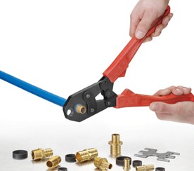
The following procedure describes the use of a PEX crimping tool:
- Square-cut the PEX tubing perpendicular to the length of the tubing. Remove all excess material or burrs that might affect the fitting connection.
- Slip one crimp ring over the end of the tubing. The ring has to be in place before the fitting is inserted into the tubing.
- Push a PEX fitting into the tubing. The fitting should be inserted into the tubing as far as is it is designed to travel.
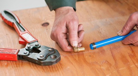
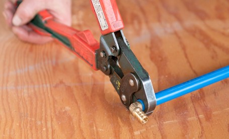
- Slide the crimp ring so that it sits 3 mm ([latex]\frac{1}{8}[/latex] in.) from the end of the tubing. Pull the handles of the crimping tool apart to open the jaws of the crimper. Place the open jaws over one crimp ring at a time. Press the crimper handles together to force the jaws together over the crimp ring.
All crimps should be tested with a GO/NO-GO gauge. If the crimp is perfect, the gauge marked GO will slide onto the crimped ring. The gauge marked NO-GO will not slide onto the crimped ring.
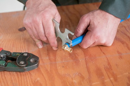
The GO/NO-GO gauge performs two tests. The crimped ring must pass the GO test and fail the NO- GO test.
If both, gauges slide onto the crimped ring, then the crimp is too tight and the pipe or fitting could be damaged. If both gauges will not slide on, then the ring is not crimped enough and could leak.
Refer to manufacturer’s literature for calibration instructions. As well, store your tool with care. It is vital for calibration that the tool be stored with the jaws just touching – the tool should NOT be under tension.
Hand PEX Expander Tool
Expanded PEX fittings make solid, permanent connections without torches, glues or gauges. The unique shape memory of quality PEX-A tubing forms a tight seal around the fitting, creating a strong, reliable connection. Note that fittings used for this system are not interchangeable with other joining methods (i.e., not to be used with crimp rings, or vice versa).
- Square-cut the PEX tubing perpendicular to the length of the tubing. Remove all excess material or burrs that might affect the fitting connection.
- Slide the PEX ring over the end of the tubing. Extend the end of the ring over the end of the tubing no more than 1 mm ([latex]\frac{1}{16}[/latex] in.). Manufacturers have added an internal ridge on one end of the ring to ensure proper amount of overhang.
- When using the hand expander tool, brace the free handle of the tool against your hip or place one hand on each handle. Fully separate the handles and slide the expander head into the tubing until it stops.
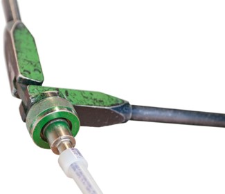
- Full expansions are necessary to make a proper connection. Bring the handles together to expand.
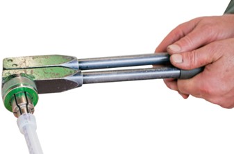
- Separate the handles, remove the head from the tubing, and rotate it one-eighth of a turn. Slide the tool head into the tubing in the newly rotated position and expand again. (Some tools have a head with a self-rotating feature.)
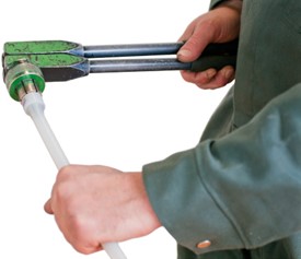
If the head is not rotated after each expansion, the segments on the tool head may cause deep grooves in the tubing. These grooves can result in potential leak paths.
- Repeat the expansion process until the tubing and ring are snug against the shoulder on the expander head (usually about 3 or 4 expansions, depending on tubing size).
- Immediately remove the PEX expander tool. As you slide the tubing over the fitting, you should feel some resistance. If the tubing reaches the shoulder of the fitting without any resistance, the tubing may be over-expanded and may require additional time to fully shrink over the fitting. The tubing and PEX ring should seat against the shoulder of the fitting for a proper connection.
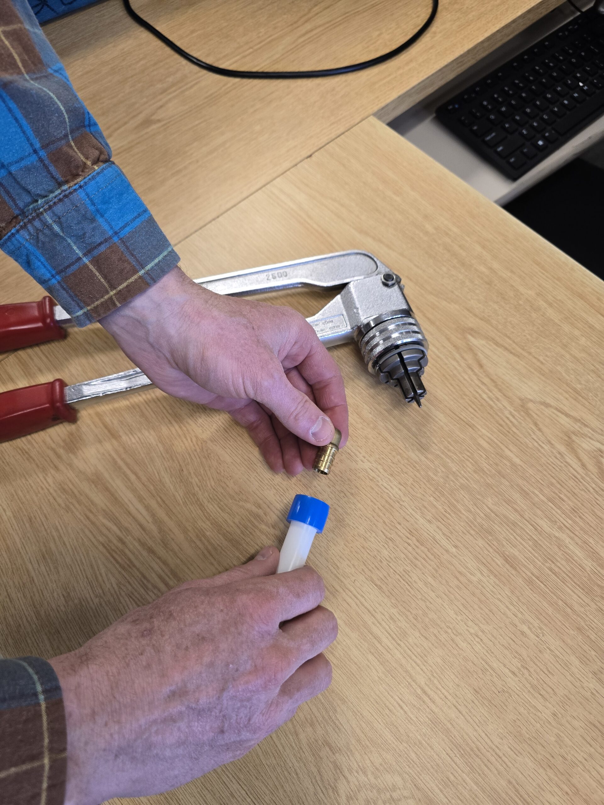
Important tips for proper PEX expanded connections:
- If the fitting does not slide into the tubing all the way to the stop, immediately remove it from the tubing and expand the tubing one final time.
Note: To avoid over-expanding the tubing, do not hold the tubing in the expanded position for an extended period of time.
- The manufacturer will recommend the appropriate number of expansions required for each size of tubing. Experience, technique and weather conditions influence the actual number of expansions (PEX becomes less flexible when cold, for example). Greater or fewer expansions may be necessary under certain conditions. The correct number of expansions is the amount necessary for the tubing and the shoulder of the fitting to fit snugly together.
- Good connections result when the PEX ring rests snugly against the stop of the fitting’s shoulder. If there is more than 1 mm ([latex]\frac{1}{16}[/latex] in.) between the ring and the shoulder of the fitting, squarely cut the tubing 5 cm (2 in.) away from the fitting, and make another connection using a new PEX ring.
Disconnecting a Brass PEX Fitting from an Expanded Joint
Brass PEX fittings are manufactured connections and can be concealed in walls, ceilings and floors. However, when necessary, brass fittings can be disconnected (plastic fittings cannot be reclaimed or reused).
- Make sure the system is not pressurized.
- Use a heat gun to heat one side of the PEX ring. When the ring is a clear colour, use a utility knife to carefully cut through the ring. Take care to cut only the ring and not the tubing. This will protect the fitting from being damaged by the knife. Remove the PEX ring from the tubing with pliers to avoid touching the hot ring. Note: Do not gouge the fitting when cutting the ProPEX Ring. Nicks and gouges in the fitting may result in leaks. If nicked, discard the fitting.
- Remove the PEX ring and apply heat directly around the fitting and tubing connection. Gently work the tubing back and forth while pulling slightly away from the fitting until the tubing separates from the fitting.
Maintenance and Troubleshooting of PEX Expanded Joints
Trouble-free installations begin with a PEX expander tool that is maintained in proper working condition. If the tool or segment fingers are damaged, it is very difficult to make a proper connection.
The following troubleshooting suggestions are designed to assist with problems in the field.
For fittings that will not seal:
- Ensure that the expander head is securely screwed onto the tool (hand-tightened). Make sure the segment fingers are not bent. If the head does not completely close when the tool’s handles are open, replace the head.
- Examine the tool for excess grease on the segment fingers. Remove excess grease prior to making ProPEX connections.
- Examine the fitting for any damage. Nicks and gouges on the fitting will cause the fitting to leak.
- Make sure the internal driver cone is not damaged or bent. Make sure the last expansion is not held in the expanded position before the fitting is inserted. The longer the tubing and ProPEX Ring are held in the expanded position, the greater the chance for a leak.
- Be sure to rotate the tool one-eighth of a turn after each expansion.
If expansion is difficult:
- Make sure the internal cone is properly greased.
If the expansion head slips out of the tubing when making expansions:
- Ensure the tubing and PEX ring are dry.
- Make sure that grease is not getting into the tubing.
- Examine the segment fingers to make sure that none are bent.
If the PEX ring slides down the tubing during expansion:
Note: this is no longer common since the manufacturers have added an internal ridge to the PEX rings.
- Ensure your hands are clean while handling the tubing. Any sweat or oils on your hands can act as a lubricant. Due to the smooth finish of PEX, any form of lubricant can cause the PEX ring to slide across the tubing during expansion.
- If you anticipate that the PEX ring may possibly slide down, position the ring slightly farther over the end of the tubing and make the first couple of expansions slowly, holding your closed hand tightly under the ring and tube. Once the ring and the tubing begin to expand together, you can continue with the normal number and type of expansions.
- Occasionally, a light amount of abrasion applied to the outer surface of the end of the PEX tube can assist in stopping the ring from sliding.
If more than the recommended number of expansions are needed to make a connection:
- Make sure that the head is hand tightened to the expander tool.
- Examine the segment fingers to make sure that none are bent.
- Be sure to completely cycle the full range of the tool on each expansion.
Cold-weather expansions:
- Temperatures affect the time required for the tubing and ring to shrink onto the fitting. Colder ambient (surrounding) temperatures will require longer contraction times.
- Warming fittings and PEX rings reduces contraction time. Put fittings and rings in your pockets prior to installation to keep them warm.
- Make expanded PEX connections at temperatures above –15°C (5°F).
- Fewer expansions are necessary in temperatures below 4°C (40°F).
Hand Threading Tools
There are many different types of hand threading tools. The choice of tool may be based on the size of pipe and/or location as well as ease of use.
Ratchet Drop Head Threader
The following describes the procedure for a ratchet drop head threader:
- Be sure the end of the pipe has been cleanly and squarely cut.
- Be sure that the end of the pipe has been thoroughly reamed to remove any burrs from the internal surface.
- Mount the pipe firmly in a suitable vise. Use a pipe support stand, if necessary, to keep the pipe aligned and level.
- Select the die head that is appropriate for both the thread form desired and the size of the pipe to be threaded. Make sure the dies are designed for that particular die head.
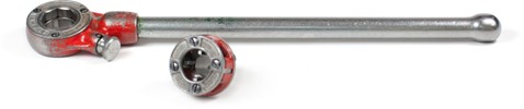
- Slip the pipe guide at the rear of the threader over the pipe
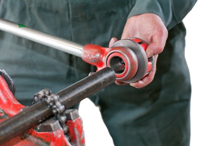
- Gently apply pressure to the front of the die head, and move the handle down while holding the die head. This will start the thread.
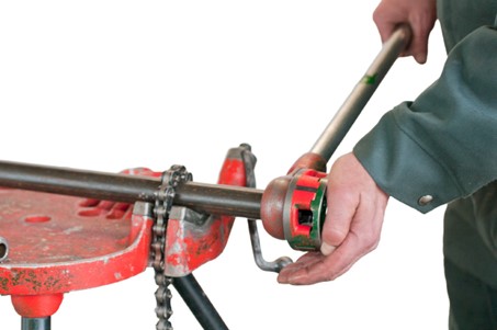
- To ensure maximum leverage, keep your weight above the handle. Do not raise the handle above the level of your waist, as this will reduce leverage. Do not let your arms do all of the work. Use the weight of your body.
- While cutting the thread, generously apply thread cutting oil with a pumping action of the oiler pistol.
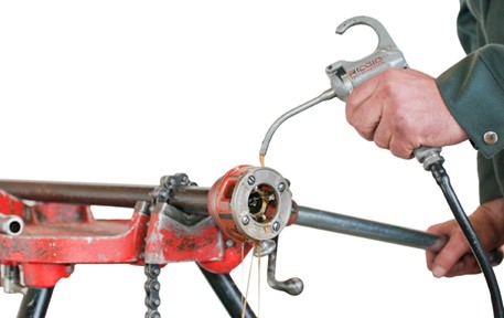
- Stop threading when the outer ends of the dies are flush with the end of the pipe. (You have now made the correct length of thread. To continue threading beyond this point would make a straight or running thread and produce an improper joint.)
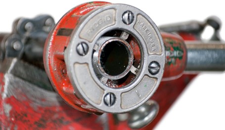
- Back off the die head from the completed thread. To do this, reverse the ratchet mechanism and turn the die head in the opposite direction to that used during the threading operation. When the dies are nearly removed from the thread, stop for a moment to be sure that you will have control over the unit when the die head is finally removed from the completed thread. In this way, neither the thread nor the threader will be damaged.
Always check a threaded pipe visually. Do not use your fingers to check a freshly cut thread because the threads are very sharp and will cut skin easily.
Jam-proof Ratchet Threader
The following describes the procedure for using a jam-proof ratchet threader:
Adjusting the Threader for Size
- Place the threader in the position as shown above.
- Unscrew the work holder by turning it counter-clockwise until the change plate is clear of the posts.
- Move the post to the pipe size desired.
- Screw the work holder clockwise until the change plate slides over the post.
- For standard thread, set the change plate between the two standard (ST’D) marks. For undersize or deep threads, set the change plate slightly above the standard (ST’D) marks.
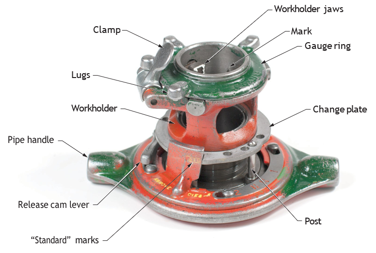
Setting the Work Holder
Turn the gauge ring until the desired size lines up with the mark on the top of the work holder.
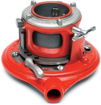
Threading the Pipe
- Be sure the release cam lever is at the close position for cutting threads.
- Making sure the pipe is held securely in the vise, slide the threader onto the pipe, work holder end first.
- Centre the end of the pipe in the dies.
- Firmly tighten the clamp screw of the work holder.
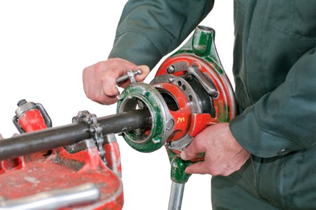
- To thread, pump the threader handle while applying thread cutting oil to the dies.
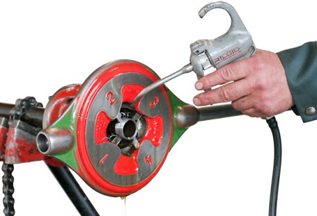
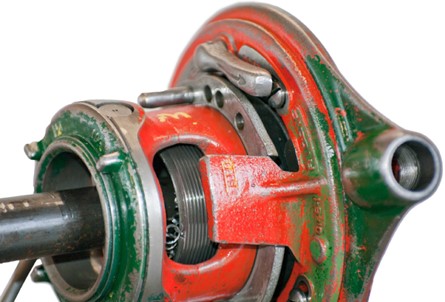
- The threader automatically releases when the change plate reaches the point shown in the following figure.
Removing the Jam-Proof Ratchet Threader from the Finished Thread
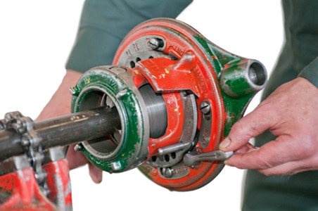
- Turn the release cam lever to the open position and spin the threader back to the standard position. Loosen the clamp screw and slide the threader off.
OR - Turn the release cam lever to the open position and loosen the clamp screw. Pull the threader straight off the pipe. No spinning off is necessary for this method of removal, but it does help prepare the tool for the next thread.
Geared Threader
The geared threader is used for threading pipe larger than 5 cm (2 in.) in diameter. The gears give a mechanical advantage, resulting in the drive shaft turning a number of times for a complete turn of the threader.
Once set up and mounted on the pipe, the geared threader can be turned with a hand ratchet, or any of the power drives using various accessories and hook-up methods.
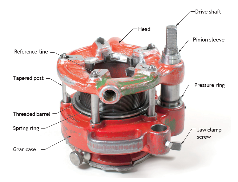
The jam-proof threader and the geared threader are similar in the fact that they use receding dies. Both have a base that clamps on the pipe with the dies set in to cut threads deepest at the end of the pipe. As threading continues, the die head turns on threads relative to the stationary base, and the dies recede to form tapered threads. Depending on how “open” the dies are at the beginning of threading, oversized and undersized threads can be cut. Other adjustments can be made to make straight (untapered) threads.

To adjust the geared threader for size:
- Place the threader on the floor or the workbench with the driveshaft up.
- Pull the knobs of the cam plate, and rotate the cam plate to the desired pipe size marking on top of the die head. Release the knobs when the locating pins drop into the holes of the selector plate. For some types of geared threaders, the size is adjusted by replacing the dies.
- Grasp the work holder and turn the square end of the driveshaft (or turn the gear case by hand) to the reference line on the guide post.
To set for standard size thread, either one of the following two reference lines may be used depending on the type of geared threader:
- Reference Line 1—Set the bottom surface of the die head at the red “Standard” line on the pinion sleeve.
- Reference Line 2—Set the upper surface of the die head, which houses the guide post, even with the centerline at the top end of the guide post.
Cleaning and Storing Threaders
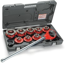
Follow these guidelines to ensure safe operation and a long life for the pipe threaders:
- Clean and wipe down threaders at the end of each job.
- Take the pipe threader apart periodically to ensure through cleaning.
- Submerge the threader parts in a cleaning solution designed for the purpose and scrub with a wire brush.
- Because cleaning agents cause tools to become dry, lubricate as necessary after cleaning. Use good quality lubricating oil. Do not use thread cutting oil (which is not a lubricant for servicing threaders).
- Inspect dies for damage or wear. First, examine the dies visually. Next, perform a test cut. If you suspect the cutting edges need regrinding, set the die aside for professional repair.
- Store dies and die heads separately on a rack in a clean, dry area. Careful storage helps prevent damage.
Pipe Taps
Tapered pipe taps can be used for making internal threads into ferrous and non-ferrous materials to connect pipe or fittings. A pipe tap resembles a shortened bolt with a slotted or squared head on one end and threads on the other end, interspersed with sharp fins. Pipe taps come in various sizes and configurations.
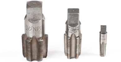
The following procedure describes the use of pipe taps:
- Apply cutting oil to the drill and drill a hole in the material that needs threads. Proper hole size is very important.
- Clean the hole with a wire brush. Remove any loose chips or pieces of metal that can result from drilling.
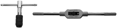
- Apply oil to the pipe tap. Insert the threaded end onto the hole and grasp it with a tap wrench.
- Turn the pipe tap clockwise one half of a turn, then turn the pipe tape counterclockwise one half of a turn. Continue this process slowly and carefully until you have advanced approximately ten tap threads into the hole. Check your fitting. If you find that it is too tight, you can run the tap through deeper.
Follow these guidelines to ensure safe operation and a long life for the pipe taps:
- Each time after use, clean off the pipe taps with a file card (a wire brush with short bristles).
- Inspect the cutting edges for wear or damage. If the edges need regrinding, set the tap aside for professional repair. Do not attempt to regrind them yourself.
- Store the pipe tap in its original container, in a toolbox, or on a rack.
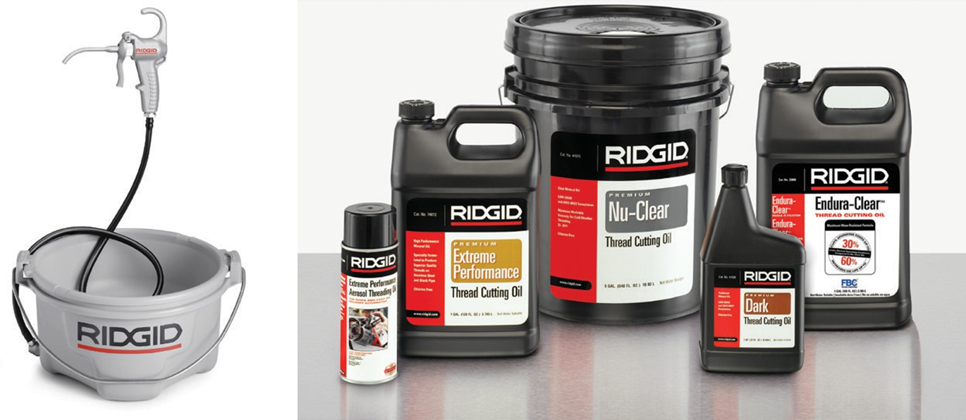
Maintaining and Storing Oilers
Follow these guidelines to ensure proper operation and a long life for the oilers:
- Metal chips and filings should be removed from the chip pan after each job and disposed of in an approved and responsible manner (ex. cleaned/drained, placed in a labelled container, and taken to a metal recycling centre) as to not contaminate soil and water.
- Periodically clean the screen with a cleaning solvent.
- Check to make sure that the level of the oil in the can is above the suction line.
- Remove the oil when the deposit in the can becomes heavy. Clean out the can with a solvent and pour in fresh thread cutting oil, making sure that the oil level is above the suction line.
- Store the full oiler in a safe, dry location away from flammables.
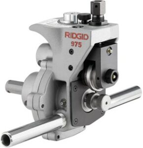
Hand Operated Roll Groover
The hand roll groover is designed to groove schedule 10 and 40 steel, aluminum and PVC pipe in 32 mm to 15 cm (1[latex]\frac{1}{4}[/latex] in. to 6 in.) sizes. It is also designed to groove 32 mm to 150 mm (1[latex]\frac{1}{4}[/latex]to 6 in.) schedule 10 and 32 mm to 50 mm (1[latex]\frac{1}{4}[/latex] in. to 2 in.) schedule 40 stainless steel pipe. With a roll set change, it can be used to groove 5 cm to 20 cm (2 in. to 8 in.) Type K, L, M and DWV copper tube.
| Material | Schedule/Type | Size Range (mm) | Size Range (inches) | Notes |
|---|---|---|---|---|
| Steel, Aluminum & PVC | Schedule 10 & 40 | 32 mm to 150 mm | 1¼ in. to 6 in. | – |
| Stainless Steel | Schedule 10 | 32 mm to 150 mm | 1¼ in. to 6 in. | – |
| Stainless Steel | Schedule 40 | 32 mm to 50 mm | 1¼ in. to 2 in. | – |
| Copper | Type K, L, M & DWV | 50 mm to 200 mm | 2 in. to 8 in. | Requires roll set change |
The hand roll groover can be used for in-place applications (pipe that is in place or mounted in a vise) or with a power drive for powered applications on the job site. The hand roll groover is not intended for production type applications.
When grooving in place, make sure that there will be enough space for the hand roll groover to fit and be operated. The roll groover will orbit around the solidly mounted pipe and requires:
- A minimum of 16.5 cm (6[latex]\frac{1}{2}[/latex] in.) clearance around the pipe to be grooved
- A minimum of 6 cm (2[latex]\frac{1}{2}[/latex] in.) pipe extending past an obstruction (such as a wall)
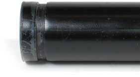
Note: the use of roll sets (groove roll and driveshaft) on both carbon and stainless steel pipe can lead to contamination of the stainless steel material from carbon steel (ferrous) particles. This contamination could cause corrosion and premature pipe failure. To prevent ferrous contamination of stainless steel pipe, use roll sets dedicated for stainless steel roll grooving only. Alternately, a stainless steel wire brush may be used to thoroughly clean the roll set when switching between materials.
The following procedure describes the preparation for roll grooving:
- Inspect the pipe to be grooved and confirm that the hand roll groover is the correct tool for the job.
- If grooving in place on existing piping, make sure that the system has been depressurized and emptied of contents. Know what the contents are and any hazards associated with them.
- Cut pipe to proper length. Make sure pipe end is cut square and free of burrs. Burrs can catch or cut gloves or fingers during grooving. Large burrs and the method of pipe cutting can affect the quality of the groove made and the tracking of the groove. Do not attempt to groove pipe that has been cut with a torch.
- All internal/external weld beads or seams must be ground flush at least 5 cm (2 in.) back from the end of the pipe. Do not cut flats into gasket seat area, this could cause leaks.
- Remove all scale, dirt, rust and other contaminants at least 5 cm (2 in.) back from the end of the pipe. Contaminants can clog the drive knurls (ridges) and prevent proper driving and tracking of the pipe while grooving.
- Make sure that the pipe to be grooved is solidly mounted. The pipe must be able to withstand the weight of the roll groover (approximately 13.6 kg or 30 lbs.), and the force and torque required for grooving without moving.
Always follow grooved coupling manufacturers’ specific recommendations for pipe end preparation. Failure to follow the grooved coupling manufacturer’s recommendations may lead to an improper connection and cause leaks.
For pipe that is in-place, remove the pipe, if possible, and groove at a pipe vise. In other cases, it may be necessary to add other temporary or permanent pipe supports. When using a pipe vise, make sure that it is secure and will not tip during use. For longer lengths of pipe, use appropriate pipe stands to support the extra length.
Mounting the hand roll groover to the pipe:
-
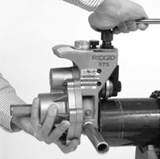
Figure 75 Holding the hand roll groover in place while tightening the feedscrew (BC Industry Training Authority, 2019). CC BY-NC-SA 4.0 Confirm that the hand roll groover has been inspected and has the appropriate roll set installed.
- Make sure that the support arms are tight in the body of the roll groover or remove them completely for better access in tight spaces. Next, install the ratchet into the feedscrew and install the extension into the manual drive square at the back of the roll groover. Make sure both the ratchet and extension are securely installed.
- Make sure that there is enough space between the groove roll and driveshaft for the pipe wall. If needed, turn the feedscrew counter-clockwise to retract the groove roll.
- Securely grasp the roll groover. Do not lift with the ratchet. Place the driveshaft into the pipe and make sure that the cover plate is tight to the end of the pipe. Tighten the feedscrew to bring the groove roll into contact with the outside of the pipe. Once the feedscrew is hand tight, use the ratchet to tighten the feedscrew an additional [latex]\frac{1}{4}[/latex] turn. Confirm that the roll groover is securely attached to the pipe and the cover plate is flush to the end of the pipe. If not, repeat the procedure. Always make sure groover is secure when used in place to prevent it from falling.
Precautions When Grooving Pipe “In Position” (in-place)
- Only drive manually for in-place applications. Do not use powered devices (such as drills or impact tools) to drive the roll groover when used in place. Use of powered devices can damage the groover and increase the risk of injury.
- Do not wear loose clothing when operating the roll groover. Keep sleeves and jackets buttoned. Do not reach across the machine or pipe. Loose clothing can become entangled in rotating parts and cause crushing injuries.
- Keep hands away from grooving rolls. Do not groove pipes shorter than specified. Do not wear loose fitting gloves. Fingers can be crushed between groove rolls or between groove roll and pipe.
- Keep hands away from ends of pipe. Do not reach inside pipe. Burrs and sharp edges can catch and cut. Fingers can be crushed between groove rolls or between groove roll and pipe.
- Always wear eye protection to protect your eyes against dirt and foreign objects. Wear steel toe footwear to protect feet from tipping tools and falling pipe. When working in place, wear a hard hat.
Follow operating instructions to reduce the risk of injury from crushing, tipping, striking and other causes.
Setting/Measuring the Groove Diameter
Note: These instructions are derived specifically from one manufacturer.
- Confirm that the equipment and pipe are properly set up. Improper pipe preparation can affect the accurate set up of the groove depth gauge. The groove roll should be touching the pipe.
- Adjust the groove depth gauge so that the correct step of the gauge is under the head of the adjusting screw. The groove depth gauge is designed for use with pipe.
- Turn the adjusting screw clockwise until the head touches the step of the depth gauge. Turn the groove depth gauge to the grooving position. If gauge is not in the grooving position, it will prevent grooving and may be damaged.
- Prepare a test groove (follow the steps for forming the roll groove, below).
- Measure the groove diameter. The best method for measuring groove diameter is the use of a pipe tape (diameter tape). Snugly wrap the pipe tape around the pipe in the groove. Make sure that the tape sits flat in the bottom of the groove, and read the groove diameter.
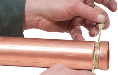
- Compare the measured groove diameter to the required groove diameter (this may be specified by the groove fitting manufacturer). If the measured groove is outside of the required groove diameter, the adjusting screw must be repositioned to give the correct groove diameter.
-
- To increase groove diameter, turn the adjusting screw clockwise.
- To decrease groove diameter, turn the adjusting screw counter-clockwise.
- Each [latex]\frac{1}{4}[/latex] turn of the adjusting screw changes the groove diameter approximately 0.5 mm (0.02 in.).
- Repeat steps 4–6 until the groove diameter is within specifications. If the first groove is too large, the groove can be adjusted and the groove made smaller.
If the groove is too small, another groove will need to be made. Proper groove diameter is important to insure connection performance. Grooves made out of specification could cause joint failure.
Due to differing pipe characteristics, a test groove should always be performed before the first groove of the day, or when changing pipe size, schedule or material. Groove diameter setting gauges are approximate only and the groove diameter must be measured to confirm proper size.
Forming the Roll Groove
- Confirm that the equipment and pipe are properly set up.
- Assume a proper operating position. Make sure that your footing is good and you are well balanced.
- Make sure that the feedscrew has been tightened [latex]\frac{1}{4}[/latex] turn.
- Remove the ratchet from the feedscrew, and securely install in the extension. (In close quarters applications, the extension does not need to be used.)
- Turn the ratchet clockwise as viewed from the back of the roll groover (this will match the arrows cast into the back of the roll groover). Watch the groover rotate and be sure that the cover plate of the roll groover stays in contact with the end of the pipe.
- If the roll groover starts to move away from the pipe end, stop rotating the ratchet to prevent the roll groover from spiraling off the pipe end and falling.
- The roll groover support arms can be pushed on to help bring the cover plate back in contact with the pipe end. If needed, remount the roll groover to the pipe.
- (See Mounting the Hand Roll Groover to Pipe.) If the pipe end is deformed, it will need to be cut off and a new groove prepared.
- Continue rotating the ratchet until the roll groover completes at least a full rotation around the pipe.
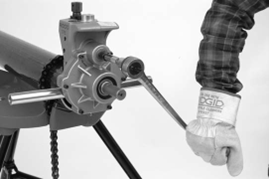
- Remove the ratchet from the extension and attach to the feedscrew. Tighten the feedscrew another [latex]\frac{1}{4}[/latex] turn. Remove the ratchet from the feedscrew and securely attach to the extension. Do not tighten the feedscrew more than [latex]\frac{1}{4}[/latex] turn per pipe rotation. Aggressive tightening of the feedscrew can cause excessive groove flare and can cause the roll groover to walk off the pipe. Continue rotating the ratchet to drive the roll groover around the pipe while monitoring the position of the cover plate to the end of the pipe.
- Continue tightening the feedscrew [latex]\frac{1}{4}[/latex] turn per groove revolution around pipe until the head of the adjusting screw stops against the top of the roll groover. Do not continue tightening the feedscrew after the adjusting screw reaches the top of the roll groover; this can damage the adjusting screw. Rotate the roll groover at least two more full rotations around the pipe after the adjusting screw reaches the top of the roll groover to insure uniform groove depth.
- Move the ratchet to the feedscrew. Securely grasp the roll groover. Turn the feedscrew counter- clockwise and retract the groove roll so that the roll groover can be removed from the pipe. Do not drop the roll groover.
- Inspect the groove.
- Make sure that the groove is fully formed.
- Check the groove diameter and make sure it is within specification.
- Check any other items required by the fitting manufacturer. If any problems are found, the groove cannot be used.
Changing Groover Roll Sets
When changing roll sets for grooving different types of pipe, refer to and follow manufacturer’s instructions carefully. Mismatched parts or rollers will cause improper grooves, which can lead to leaks and possible injury.
Hand Roll Groover Maintenance
Follow these guidelines to ensure safe operation and a long life for hand roll groovers:
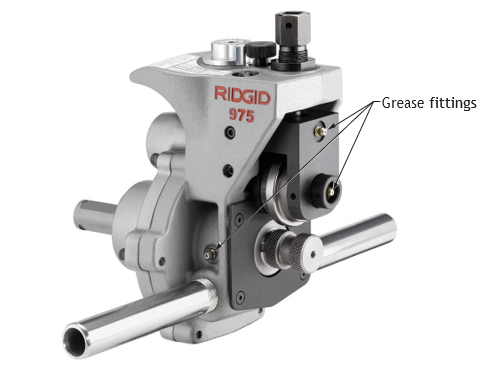
- Lubricate the hand roll groover with good general purpose grease once a month.
- (Grease fittings are located on the side of the operator’s side of the base, the front of the slide block, and the end of the groove roll shaft.)
- Add grease until a small amount is pushed out. Apply a light coat of grease to the feedscrew.
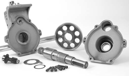
- The gear box of many hand roll groovers has adequate grease for its service life and does not require the addition of any grease unless the gear box is opened.
- Clean the driveshaft knurls with a wire brush on a daily basis or more often, if needed.
 Self-Test B-1.2: Use Hand Tools
Complete Self-Test 1.2 and check your answers.
If you are using a printed copy, please find Self-Test B-1.2 and Answer Key in the Appendix at the end. If you prefer, you can scan the QR code with your digital device to go directly to the interactive Self-Test.

References
BC Industry Training Authority. (2019). Piping trades apprenticeship program: Use Tools and Equipment—Level 1 harmonized [Binder]. Crown Publications, Queen’s Printer for British Columbia. https://www.crownpub.bc.ca/Product/Details/7960000261_S
Camosun College. (2019). Line C: Tools and Equipment—Competency C-1: Describe Common Hand Tools and Their Uses (Rev. ed.) [Learning guide]. BCcampus. https://collection.bccampus.ca/resource/BzEe9fcq/
Camosun College. (2015). Trades Access Common Core Competency C-1: Describe Common Hand Tools and Their Uses. Victoria, B.C.: Crown Publications. Download for free from the B.C. Open Textbook Collection (https://open.bccampus.ca/browse-ourcollection/find-open-textbooks/).
Media Attributions
All figures are sourced from Industry Training Authority (2019) and/or Camosun College (2019) and are used under the Creative Commons Attribution 4.0 (CC BY 4.0) licence unless otherwise noted. Images copyrighted by the BC Industry Training Authority are licensed under a Creative Commons Attribution-NonCommercial-ShareAlike 4.0 (CC BY-NC-SA 4.0) licence.
RIDGID tool images are used with permission from Emerson Professional Tools. Some of these images may have been carried forward from SkilledTradesBC learning resources; however, permission has been obtained directly from Emerson Professional Tools for their use here.
a finishing technique where a file is held sideways across the workpiece and pulled or pushed along the surface. This method removes small amounts of material and helps create a smooth, flat finish on metal surfaces. It is commonly used to improve surface quality after rough filing. (Section B-1.2)
The flat or angled surface of a tool that does the cutting. It is the part of the tool that comes into contact with the material and removes small pieces as the tool is used. Cutting faces are found on tools such as chisels, drill bits, and cutting blades. (Section B-1.2)
A flexible measuring tool, often made of paper, plastic, or metal, that is wrapped around a pipe to mark a straight and even cutting line all the way around it. It helps ensure the pipe is cut square (perfectly straight) across its diameter. (Section B-1.2)
A tightly wound metal spring that slides over or inside soft tubing to help it bend without kinking or flattening. It supports the tubing while it is being bent so the curve stays smooth and the tube keeps its round shape. (Section B-1.2)
A handheld tool used to bend metal tubing by applying steady pressure around a curved form. It supports the tubing during the bend so it keeps its round shape and does not kink or flatten. (Section B-1.2)
The small amount of extra length that appears when a tube or pipe is bent. Because the material stretches slightly along the outside of the bend, the total length of the tubing becomes a little longer than the straight measurement. (Section B-1.3)
A measuring tool used to quickly check if a part is the correct size. One end (the “go” side) should fit into or onto the part if it is the right size, while the other end (the “no-go” side) should not fit. If the “go” side fits and the “no-go” side does not, the part is within the correct limits. (Section B-1.2)